GTMS leverages an open-source software called XFLR5 for design and simulation of 2D Airfoils. Download the latest or most recommended version. Your computer will likely give you a warning that the software isn't safe. It is, just hit the more info button to allow it to run. Follow the steps below to create and analyze a two-dimensional airfoil.
Open XFLR5. You'll be met with a blank screen
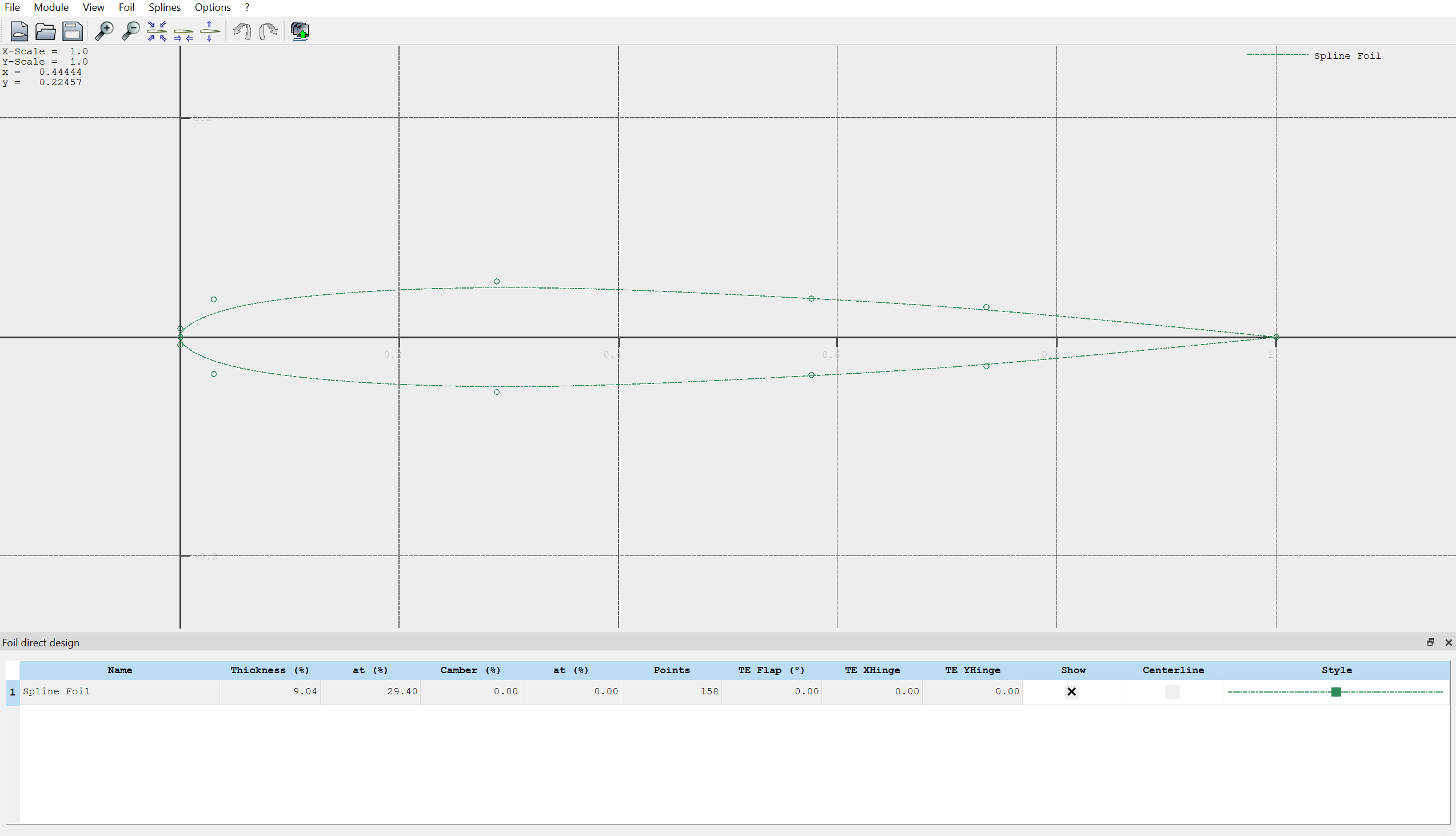
Navigate to Module -> Direct Foil Design at the top left of the screen. You should see an interface that looks like this:
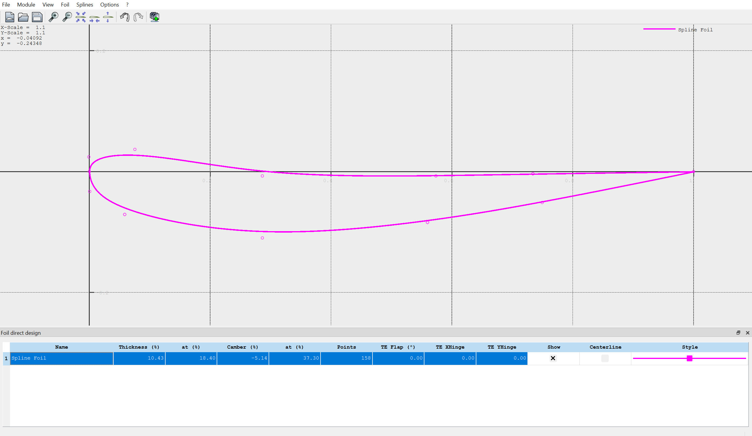
Click to drag the points you see on screen to make a new spline shape. Yes, it will likely look like a mess your first time making one. You likely barely know what a "good" airfoil is supposed to look like. That's okay! We have resources for that, and this tutorial is just to get familiar with the design procedure. Here's what mine looks like, if you want a reference:Note that you can change the appearance of your spline by clicking on the "style" tab on the table below your airfoil.
Navigate to Splines -> Store Splines as Foil in the top left. Enter a name with the naming convention (initials)_(type)_(descriptor). Type for our case is sort of ambiguous, but know that "primary", "secondary", and "tertiary" are common designations for the first, second, and third elements of a wing. They are usually abbreviated as "P", "S", and "T". Equally as valid is element 1, element 2, and element 3 which shorten to E1, E2, and E3 respectively. I named the above airfoil "JD_E3_Example".
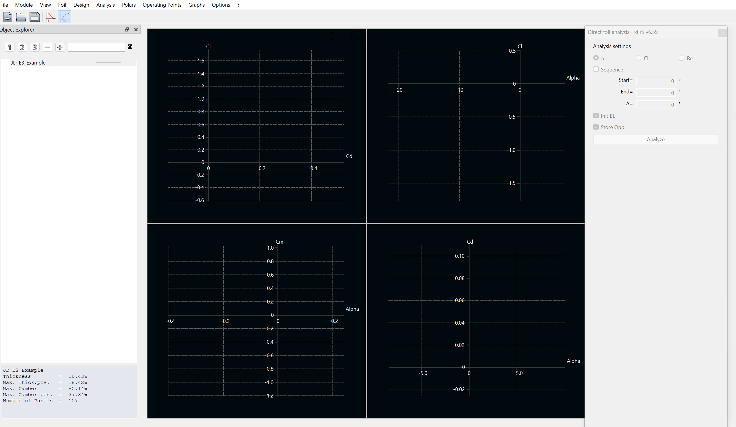
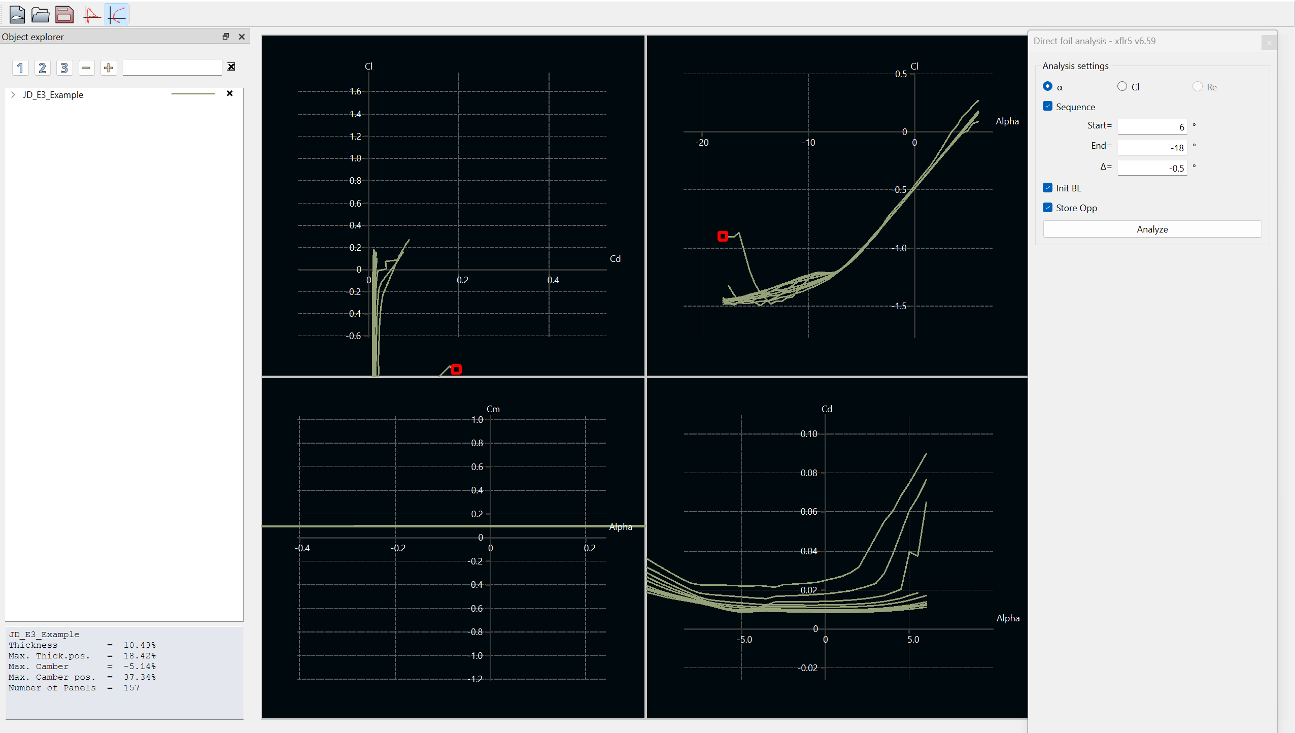
Navigate to Module -> Direct Foil Analysis. You'll see an interface that looks like this:
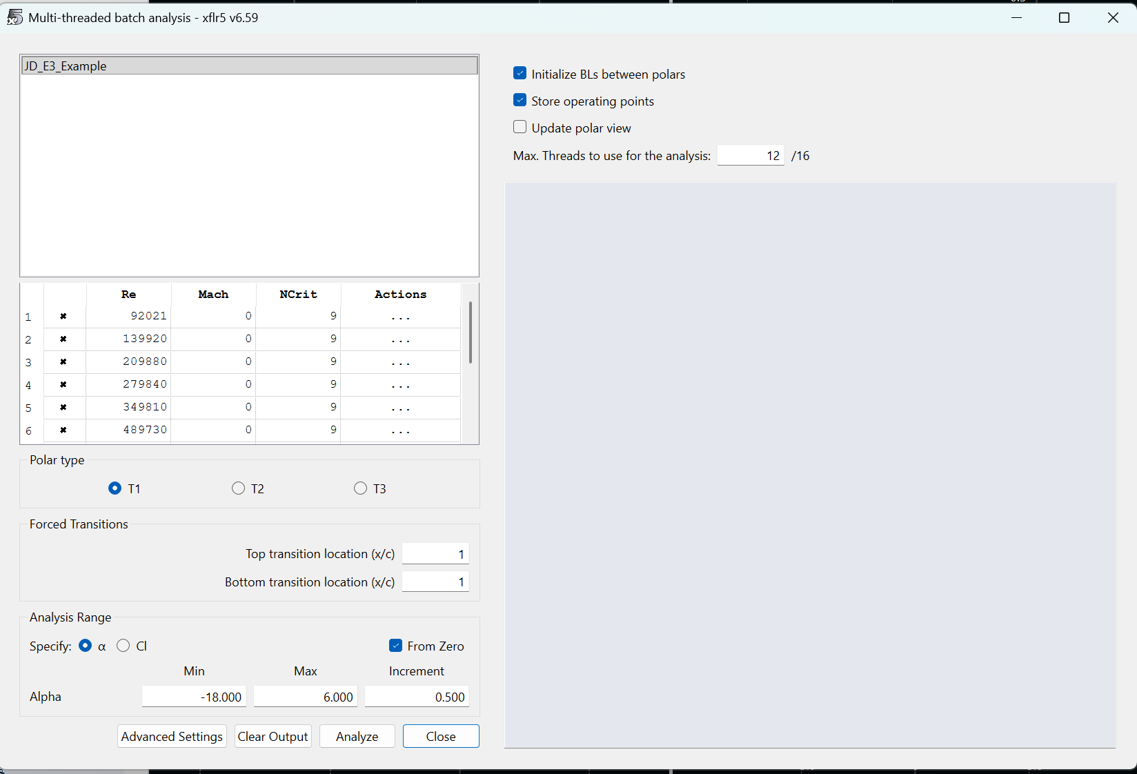
Navigate to Analysis -> Batch Analysis. It may be a bit confusing for those less experienced from here. Batch analysis allows us to test our airfoil at multiple angles of attack and at multiple Reynolds Numbers. The UI will look like this: First, set Min Alpha to -18 and Max Alpha to 6. This defines the range of angles of attack we simulate. Change the increment to 0.500. For Reynolds Numbers, calculate a good range of numbers between 10 and 60 mph at sea level conditions. Assume a characteristic length of 1 m. Use the 1976 Standard Atmosphere Calculator to determine dynamic viscosity and density at sea level. One of my personal favorite websites that one, love the little fishes they have at the top. Click the checkbox for Initialize BLs between polars and Store operating points. Change the number of threads such that your computer has four threads available. finally... HIT ANALYZE
Exit out of the batch analysis window. You should see the graphs populated with data like so: Now what? You just completed your first airfoil simulation! Click and drag the graphs to bring more data into view. Click the dropdown on the left hand side (in the screenshot, the row that says "JD_E3_Example". Clicking the x's will show or hide the data for a specific Reynolds Number of a specific angle of attack point.
SAVE YOUR PROJECT. I didn't, literally just as I was making the tutorial, and lost my progress.
Check-in questions before moving to the next section:[edit | edit source]
What is the general trend of Cl versus alpha? Linear? Exponential?
What is Cl or Cd anyway?
What is the trend for Cd versus alpha?
How do these relationships correlate? E.g., what is the relationship between Cl and Cd? Is there a point at which that relationship changes?
How do the trends differ for different Reynolds Numbers?
How can I improve airfoil lift? How can I reduce drag?
Now that you've designed an airfoil and completed analysis on it, its time to take it to Solidworks. Follow the steps to obtain a generic sketch in Solidworks with your airfoil profile.
Clone a local view of "Airfoil-.DAT-Inverter" from GitHub. This section will require you to create a GitHub enterprise account with your Gatech account information. Once this account is created, message a lead asking for GitHub access. They'll need to send you an invite to join the organization. Once you're on, here's the steps to make a local view:
Open command prompt and navigate to a directory in which you want this Matlab tool (cd "C:\ahoosian45\Example_Folder\")
Run the command "git clone https://github.com/username/repo.git subfolder-name", where the URL is the URL of the repository online
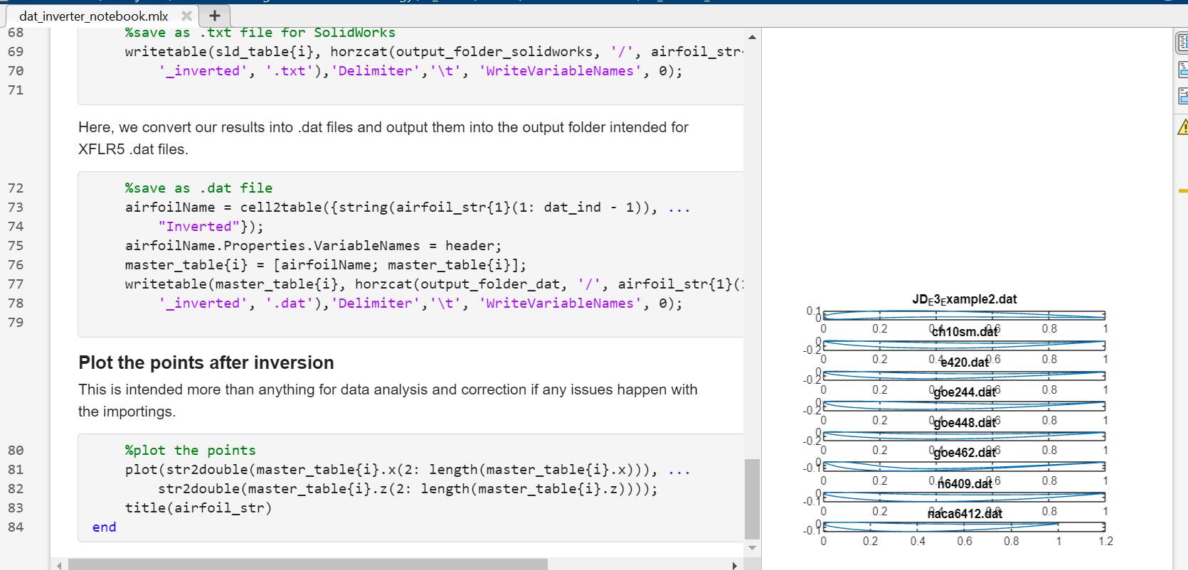
Open "dat_inverter_notebook.mlx" in Matlab. This is the main live script that will take the exported .dat file from XFLR5, scale the values, and convert to .txt which is readable by Solidworks.
Lets go back to XFLR5. To export your spline, navigate to Splines -> Export Splines to File. Save the .dat file with the same name as the spline to the directiory "...Airfoil-.DAT-Inverter/input_airfoils"
Hit run on the entire "dat_inverter_notebook.mlx" script. At the end of the script, you'll see a bunch of graphs with some example airfoils and your new airfoil. If you don't see your airfoil, you did something wrong.
Open Solidworks. If you haven't already, follow this onboarding document to setup the proper GTMS Solidworks Templates
Create a new GTMS part
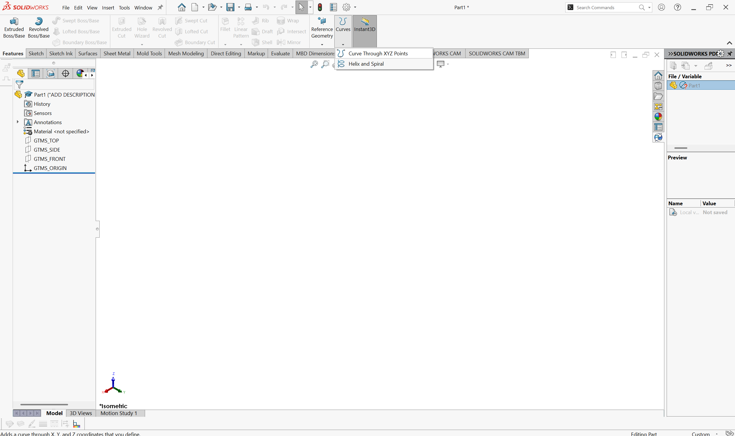
Navigate to Features -> Curves -> Curve through XYZ Points. You are not creating a sketch yet. curve import is a feature outside of sketch creation.
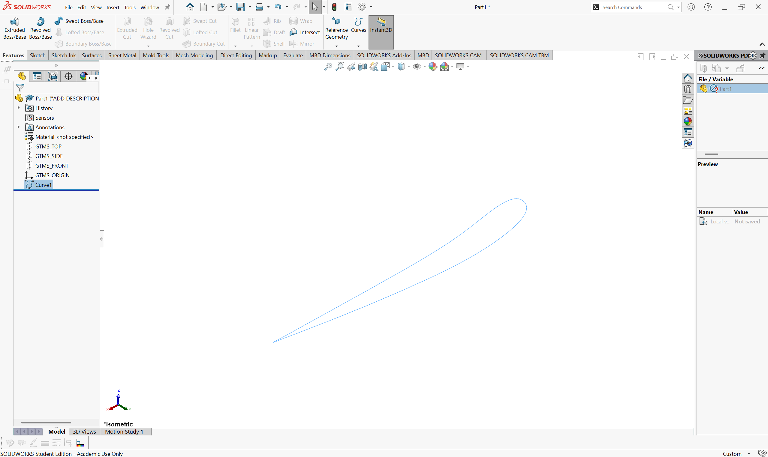
Hit "Browse" and navigate to the folder "......Airfoil-.DAT-Inverter/solidworks_txt". You should see your converted spline .txt file in this folder. Select it and hit ok
The airfoil profile is the only import component necessary to construct CAD of your front wing. This generally applies to all aerodynamic parts, as any other element you need can be constructed by curvature you design.
DISCLAIMER: CAD is hard. This tutorial is not intended to be an "introduction to CAD". The steps should be clear enough to follow as a beginner, but at times will likely feel un-intuitive if you're new to CAD.
When in a design cycle, you really should try to draw or document your ideas before you CAD them. There's a few reasons as to why;
Figure out what it is you're actually thinking. Too often, even with myself, aero engineers have an idea for a part, spend a day trying to get the CAD to work, and end up with something completely different to what they originally thought of. Corners are often cut just to make the part quicker. When you can help it, avoid doing this by sketching so you know exactly what CAD you want. What dimensions are important? What curves will define my part? Decide this before throwing darts at the CAD board.
Decide on structures and manufacturing points. Can we even build this? It's okay to design parts that are floating for aero development, but you should have at least one idea in your mind on how this would eventually be attached to the car. There is no point otherwise.
Is it stupid. Stupid is relative, but sometimes drawing out a part makes it a LOT more clear as to what you can accomplish. Say you want some crazy endplate design. When you try to draw it out, you should be able to see how the dimensions of the design work with each other, and what parts need to be compromised. Do things actually align with, say, the tire or the sidepod inlet? If, instead, you draw it out and what you're able to achieve looks like spaghetti in space, its probably dumb to some degree.
tl;dr do a drawing so you know the part works before CADing. No specific tips or steps here, every design has their own process.
We'll be working with the CAD file you've just imported your airfoil into. The first step in a design is understanding your constraints. We'll put these into your part now.
The "bounding box" is a design space for aerodynamic components in FSAE. The box is outlined in section T.7 of the FSAE rules. The box is largely dictated by wheel position, so we must define that first.
Create a sketch on "GTMS_TOP". The origin of the part is located on the ground plane and is on-plane with the vertical front axle plane. This means that we can define track width using the origin as the midpoint. Create a centerline that does so.
Dimension the line to 48 inches. This is the base track width for the majority of our cars.
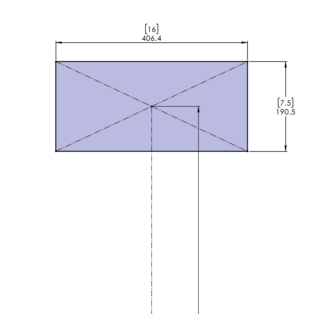
Create a rectangle based on the size of our tires. We use the 16x7.5" Hoosier R20's (Last updated 10/27/2025). This sketch serves as the "shadow" of our tire.
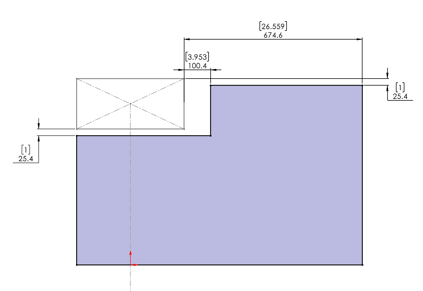
Create another sketch on "GTMS_TOP", which represents our ground plane. Make this sketch while referencing the rules to ensure the bounding box lines up. Ask yourself what is the reason for adding 1 inch of clearance to the actual rules.
Extrude the box upwards by 250 mm minus 1 inch
Make a sketch on the top of the new box. Highlight the top of the box and go to Sketch -> Convert Entities
Use the trim and line tools to create a rectangle that looks like this:
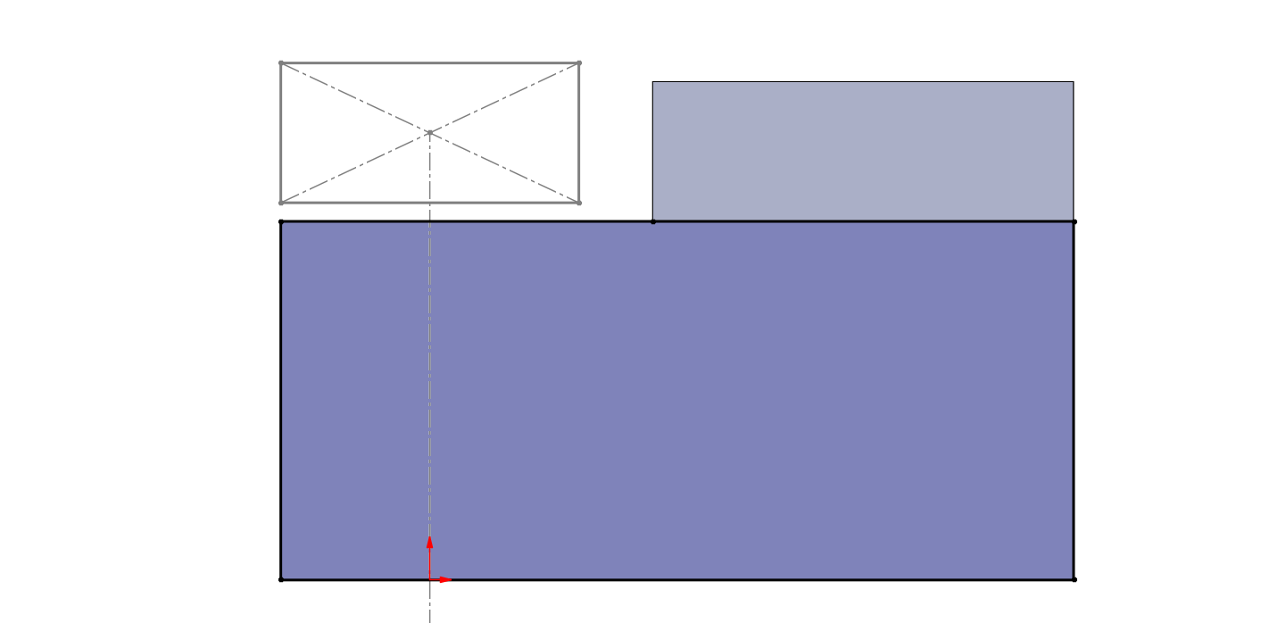
Extrude this box by 250mm
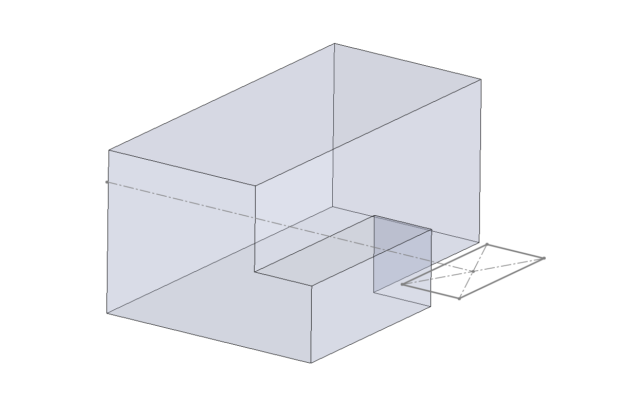
Go to solid bodies and right click the box. Make the box transparent.
Your front wing bounding box is now complete with 1 in. tolerance in all dimensions
Another crucial constraint we need to model is interferences with the rest of the car. Below is a methodology for importing reference surfaces for the rest of the car into the part file.
ASIDE: The following process is typically done within some larger assembly that already exists, e.g. F26_AE_SimAssembly. For this tutorial (and since PDM is down while I'm making this), we'll use a generic assembly.
Create a reference assembly. Any normal assembly will do. We will delete this reference assembly after use.
Include your front wing part and an part you want as a reference into the assembly. This is done using this command:
MATE BOTH PART ORIGINS TO THE ORIGIN OF THE ASSEMBLY. This is the most important part. We'll be utilizing something called "model in place" where the origin for every part in our assembly is shared. Feel free to look it up and how it's different from modeling with mates.
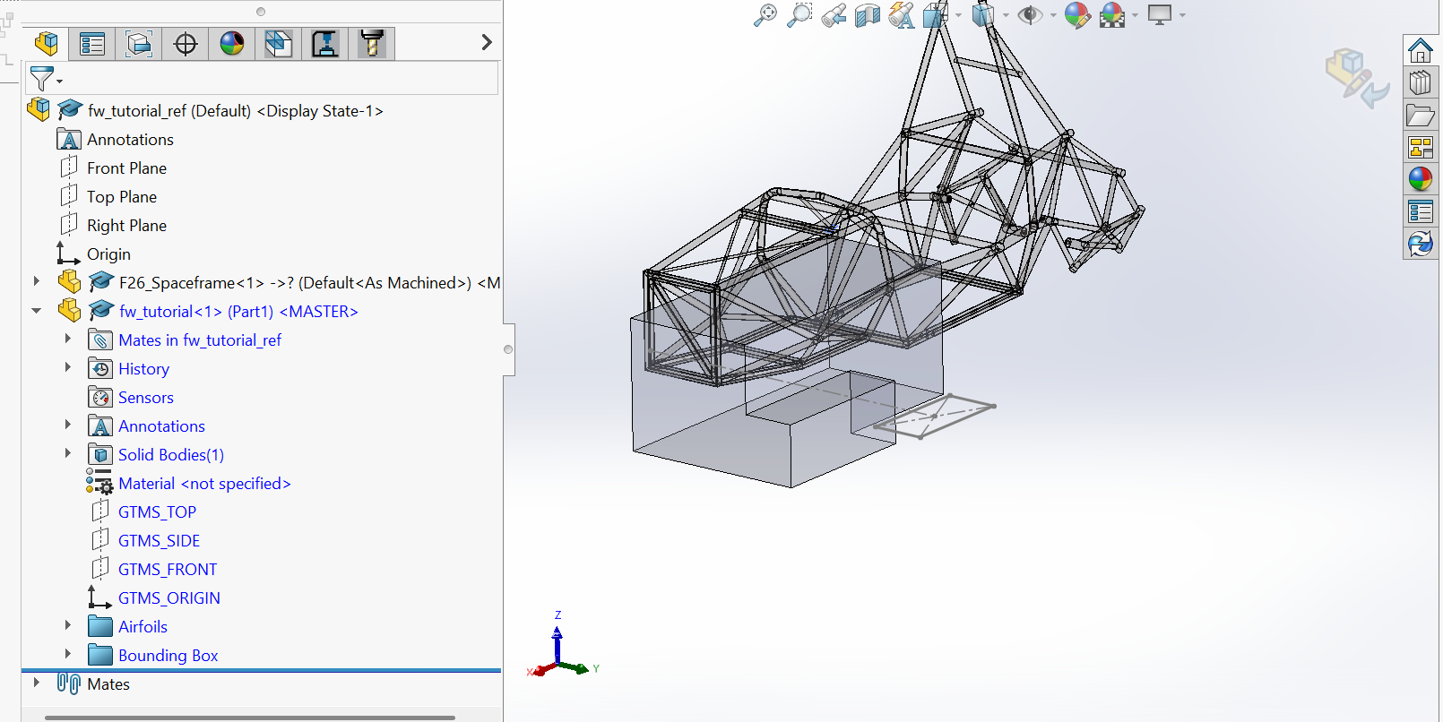
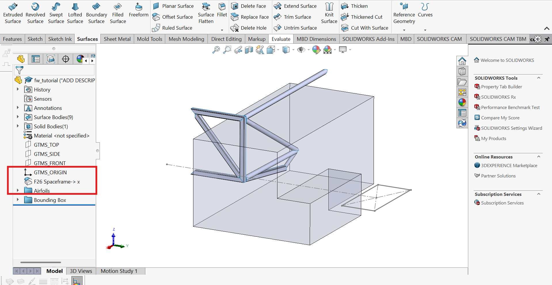
Right click the front wing file and hit "Edit Component". The icon will be a yellow Tetris piece with a blue square and a pencil. When selecting this, your part being edited should show a blue feature tree like so:You'll notice a few things here. First, I am using the F26 spaceframe as my only reference part. Also, you'll see that this part is now transparent. This means that the part is in the assembly but not being edited.
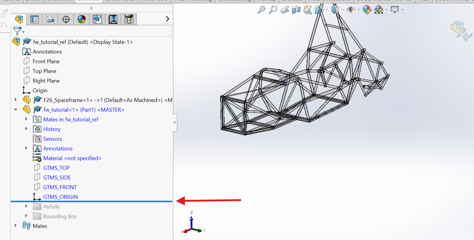
Roll back your feature tree so that no parts are showing
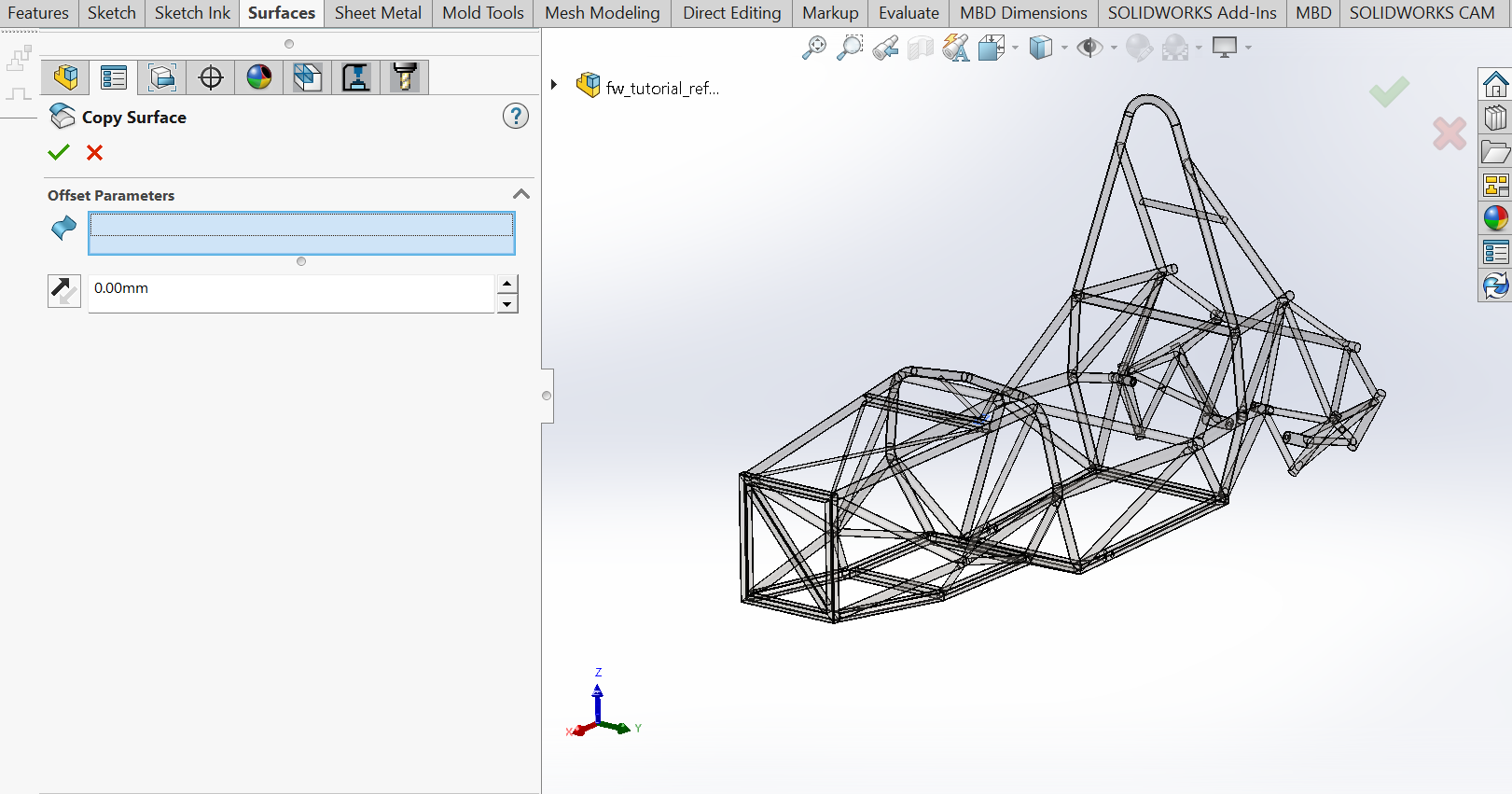
Go to the "surfaces" tab and hit "offset surface". Set the offset distance to zero. You should see that instead of "offset", the operation says "copy".
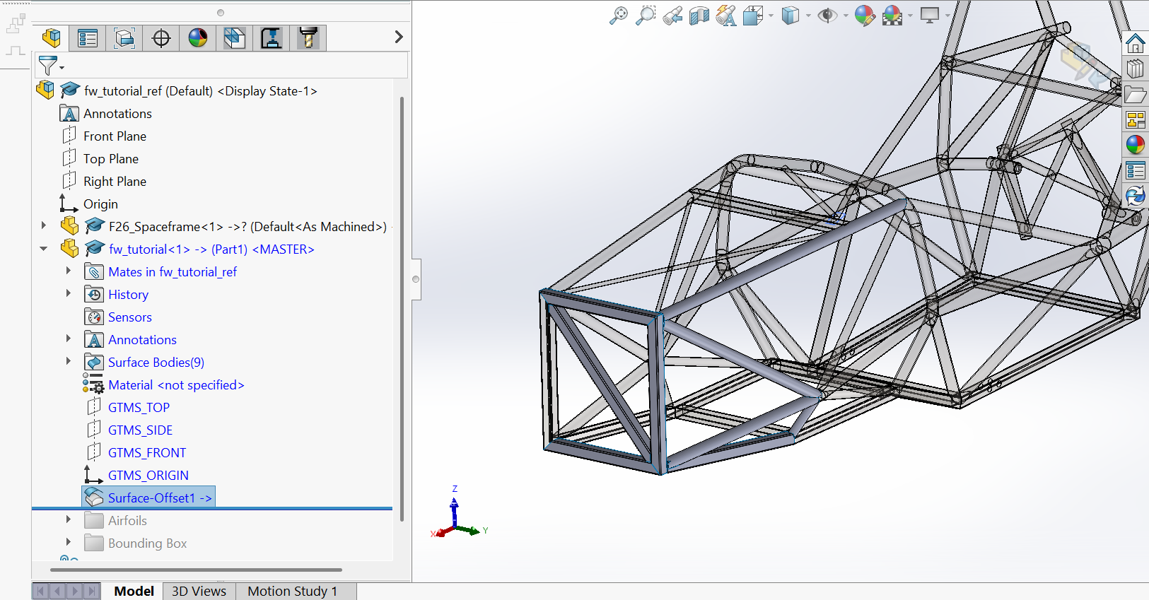
Click on everything! Yes, you have to individually select any part of the existing geometry that you want to be able to reference or see when designing your front wing. Sorry. When this is done, hit the green checkmark. Any part you selected should appear in solid grey, as these surfaces are now copies that are contained in your front wing file.
If everything looks good, close the editing window in the assembly and navigate back to your part file. If not, edit the offset geometry until you have every surface you want.
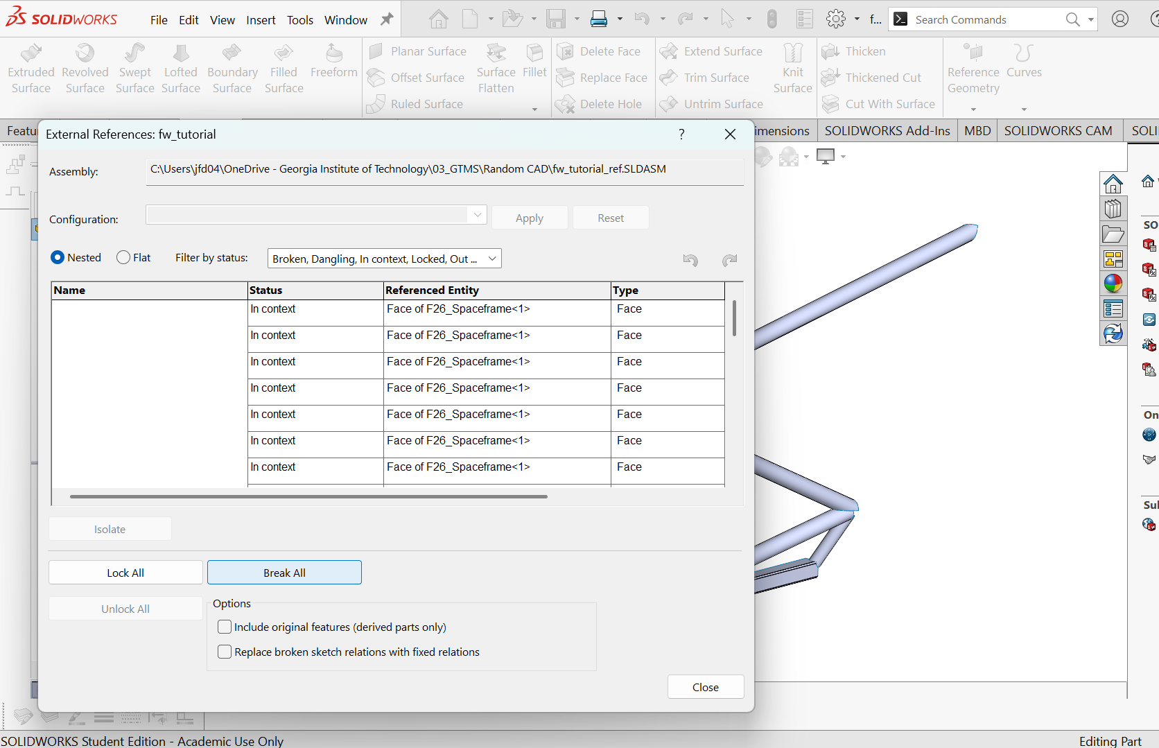
Right click on the part, navigate to "External References" and hit "break all". This ensures that any further adjustments made to the original geometry do not affect your part file. You might be thinking right now "Hey stupid internet man, wouldn't I want the references to update to see if my part contacts anything?" To that I would say, firstly, I'm not just Internet man. Secondly, yes, in a perfect world you have references that update with any part. In practice, this rarely works. Members of the team often will start to use a new part, break the original part, or remove a surface from their part that you were referencing. All of these things will cause your reference to break, which risks the rest of your part breaking if you used the reference in any way outside of a visual reference. TL;DR count on CAD getting broken and break references in advance. Confirm your part still works and clears before manufacturing.
Rename your part to identify it. This is important considering this reference has been broken forever.
Freaking finally, the fun part. Sort of. A good wing design (or any aero part) will have a good amount of reference geometry to define airfoil cascade sections and lofting areas in advance. What that means is more boring plane work before actually constructing the part. Trust that you will thank yourself for doing these setup steps.
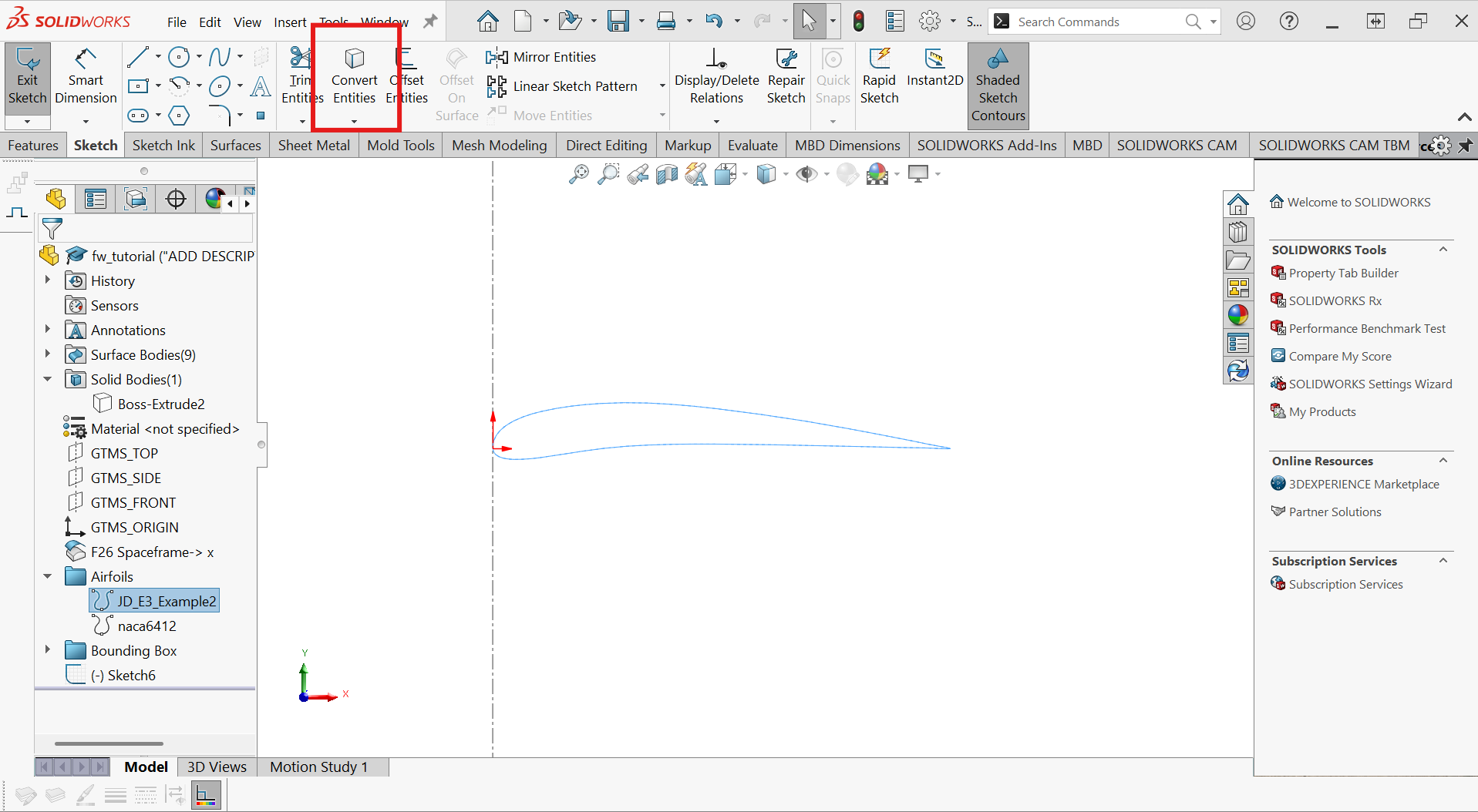
Your airfoils aren't usable in their current "curve" format. We'll need to transfer them onto a sketch. Make a sketch on GTMS_TOP. Highlight the airfoil you want and hit "Convert Entities"
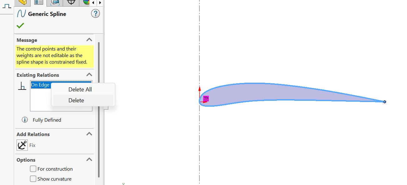
You'll see that the curve is now a part of your sketch. Delete the "On Edge" relation.
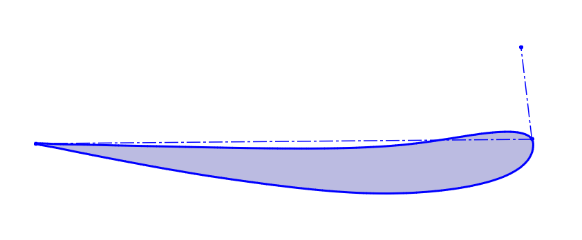
We now begin to define our airfoil in the sketch. This step is crucial for properly CADing airfoils. Begin by drawing a construction line from the leading edge upwards. Draw another construction line from the leading edge to the trailing edge.
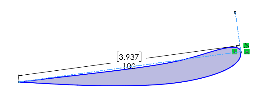
Add a perpendicular relation between the two lines. Then add a tangent relation to the vertical line and the airfoil. Finally, add an arbitrary dimension to the horizontal line. Notice that the horizontal line now defines your chord and the dimension you added is the chord length.Try to adjust this airfoil by moving it from different points. You should notice that it can only be translated, not scaled in any way.
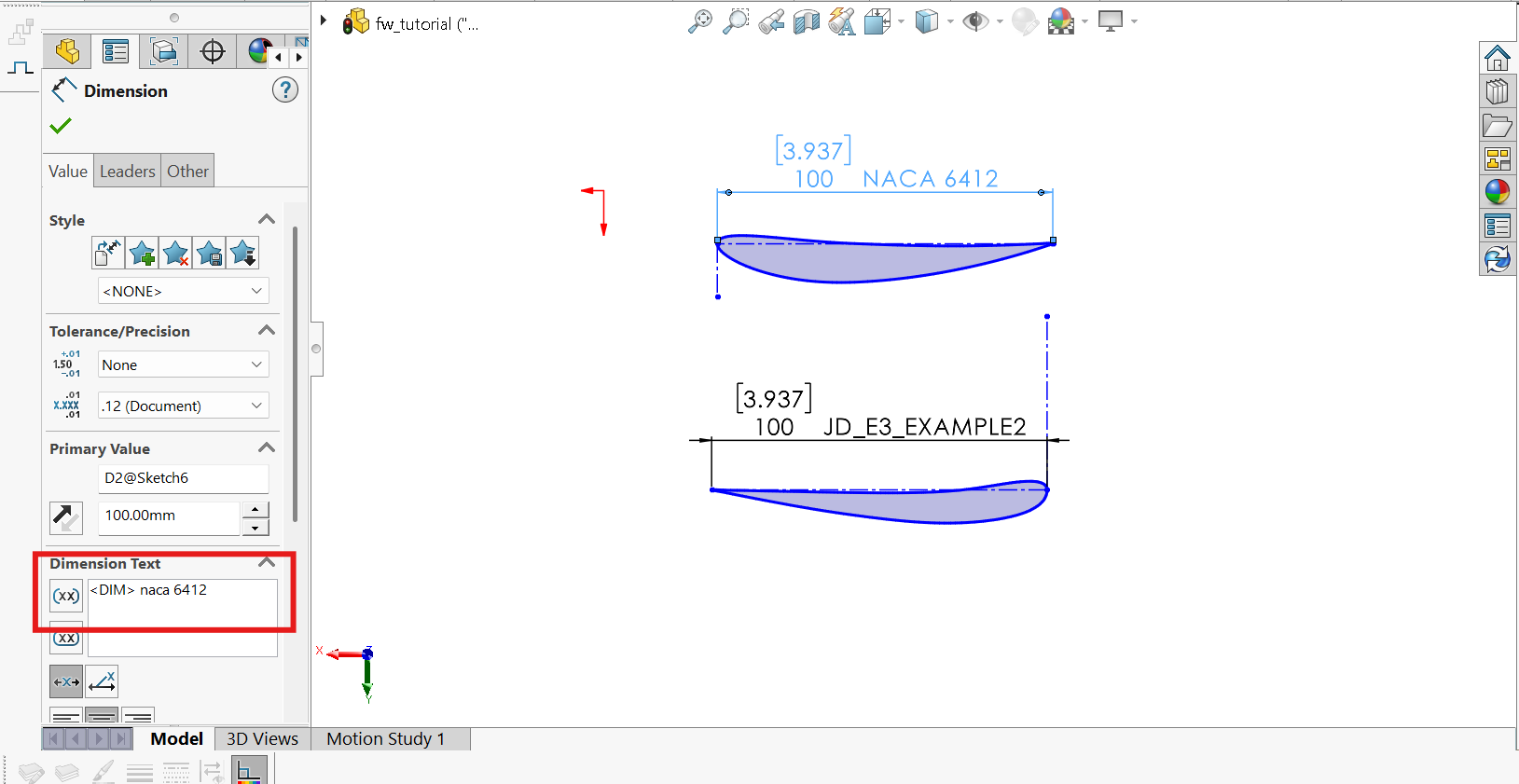
We have, like, never done this, but PLEASE label your airfoil with its name in the sketch. Without it, no one has any idea which airfoil they're seeing. To do this, simply write the name of the airfoil in the "Dimension Text" box of your chord length dimension:Notice that the NACA 6412 is also a part of this sketch. It's common to include all of the airfoils in a single arbitrary sketch. That way, when creating airfoil cascades, you can just copy the curve from the sketch and use it in the cascade sketch. I'll let you figure out how to import the NACA 6412. Hint, its one of the example airfoils in the DAT_inverter notebook
"Reference Planes" (as I call them now apparently) are planes that define the 2-D sections of your 3-D geometry. We will define four reference planes and thus four different cascade profiles in the wing.
From this point on, the tutorial will be dependent on your reference geometry and the design you want. You can choose to follow exactly, or go your own way. They should make a song about that.
Create a reference plane on the middle plane. Just so we don't need to use the GTMS_SIDE plane all the time.
I created three more planes. One plane is offset 4 in from the chassis. Another is coincident with the inboard plane of the bounding box. The last is offset 2 in from the outboard plane of the bounding box to allow room for the endplate.
Define a minimum ride height plane. This is incredibly necessary when sketching your airfoil cascades. This plane sets the lowest point in your wing (not by rules, but by vehicle dynamics / scraping). LOTS of discussion and foresight should be used in finding the value of this plane. So, for now, lets say its, uhhh, i dunno, 2.5 inches from the ground?
You'll define an airfoil cascade for each of the planes you generated. A "cascade" is a section of multiple airfoils. I'm not teaching any aerodynamics in this tutorial, but I'll be touching on why my cascades look like they do.
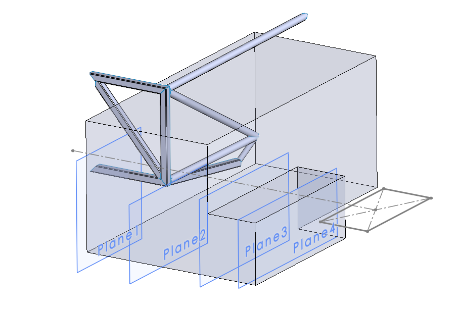
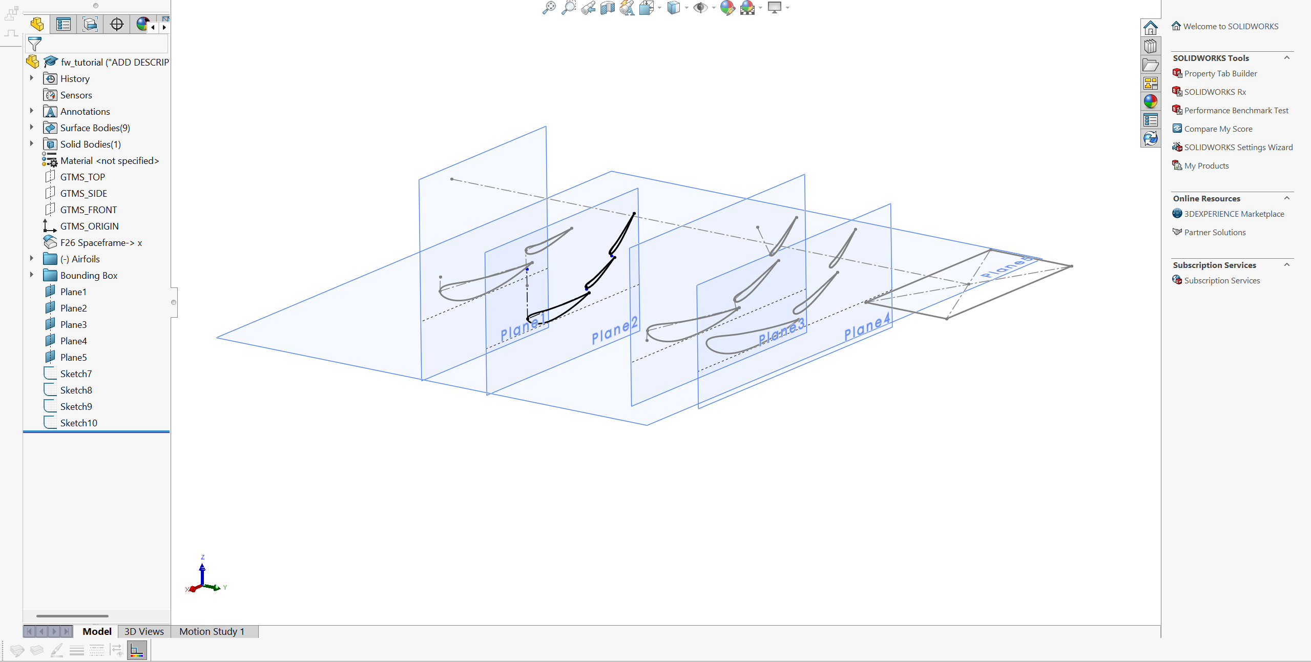
Create a cascade sketch for all of your airfoils. I'm attaching a picture of my four cascades and the sketch view of one of them. These are my pointers for making the sketches:
The leading edge of elements behind another element should be slightly forward and slightly above the trailing edge. This is a fundamental design feature for airfoil cascades. Ask yourself why this is. How can we accelerate flow (thus lower pressure) beneath an airfoil? What happens in a converging duct? What's an adverse vs. favorable pressure gradient?
Don't make your airfoils tangent to the minimum ride height plane as it can provide undesirable results. The spline from points makes tangents behave in an unintuitive way. Instead, just visually check your airfoil is above the plane
Use the chord lines to define the angle of the first element with respect to ground. Define the angle of each following element with respect to the chord of the element before it
Use Ctrl+c and Ctrl+v for copy paste of the airfoils. Its that simple if you've make the initial airfoil sketch correct.
Use convert entities if you want to use the same airfoil cascade you already sketched on another plane. I did this for planes 3 and 4.
We will begin construction of "E1", otherwise known as "mainplane", "primary", or "The first one that's typically the biggest". Name it however you like. This part will not feel intuitive but:
Make a sketch on plane 1, the plane of the inboard cascade. Do "convert entities" on the first element in the cascade and its construction chord line.
Trim the part of the element above the chord line, so only the bottom section is remaining. So basically, if you hide the original cascades, you'll only see the bottom of the first element. We do this so we can construct the top and bottom sides separately. This helps with complex lofting profiles and makes trailing edge truncation and mold design easier. We'll get there. Eventually.
Repeat this step for every airfoil cascade you made.
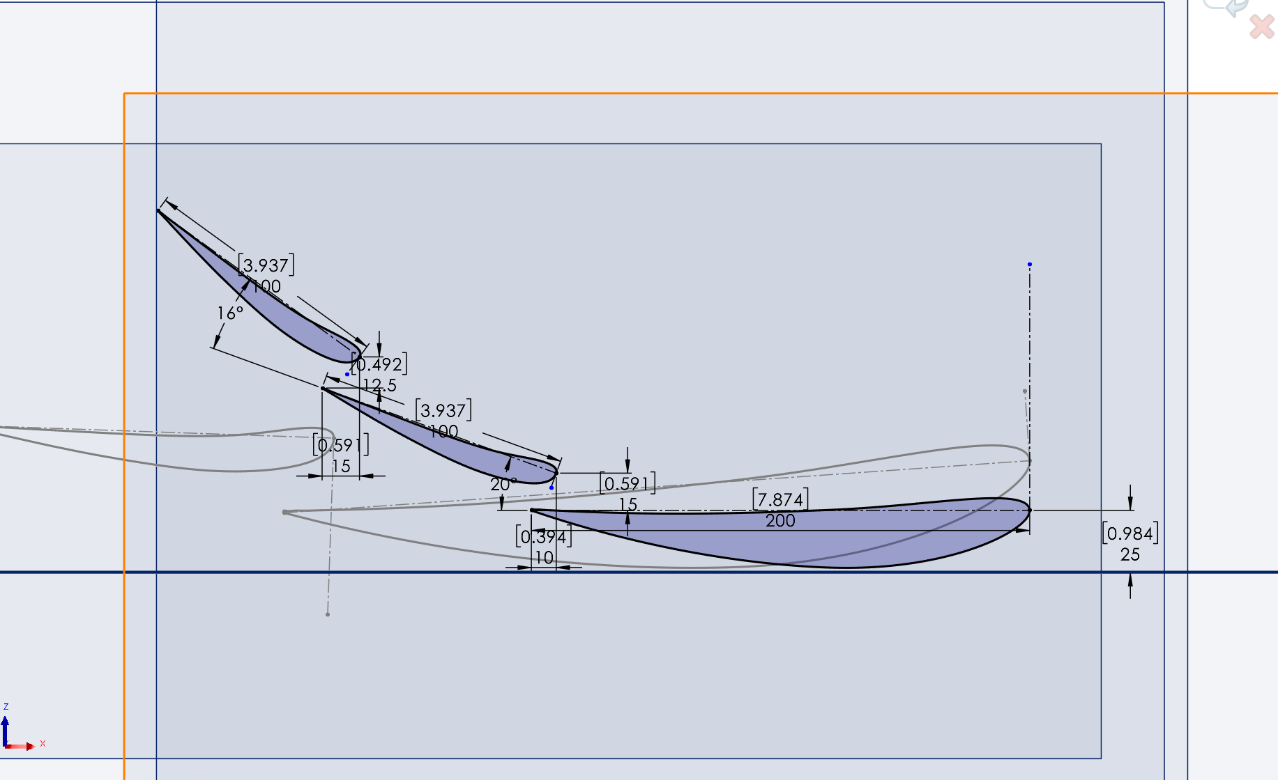
The loft that we will eventually do will require these sketches as the profiles, but will also require some guide curves. We will use the spline feature on a 3D Sketch to create these guide curves
Navigate to the sketch tab and hit the dropdown under "Sketch". You'll see an option for 3D Sketch. When you hit it, you wont get any option to select a draw plane since the drawing is in 3D
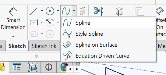
Navigate to the spline button and hit it, show here:
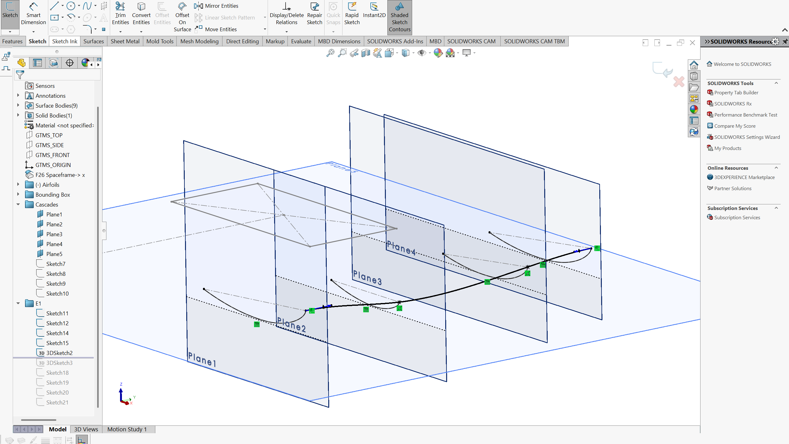
Click on the leading edge point of each of the half airfoil sketches you just made.
You should see some weird looking arrows at each point when you click on the spline. If not, let me save you like 2 hours of figuring out why through youtube videos from 2013:
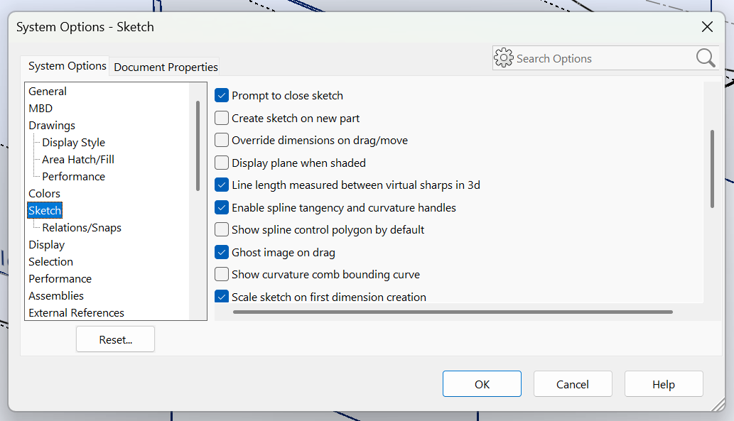
Go to Tools -> Options
Find the sketch menu and select "Enable spline tangency and curvature handles"
Move these arrows however you like. You should want the surface to remain smooth, but this is where any crazy lofting of the element is defined if you want that. You can also constrain them to the y-axis, which is best used when you want your part to be continuous when you mirror it.
Repeat this for the trailing edge.
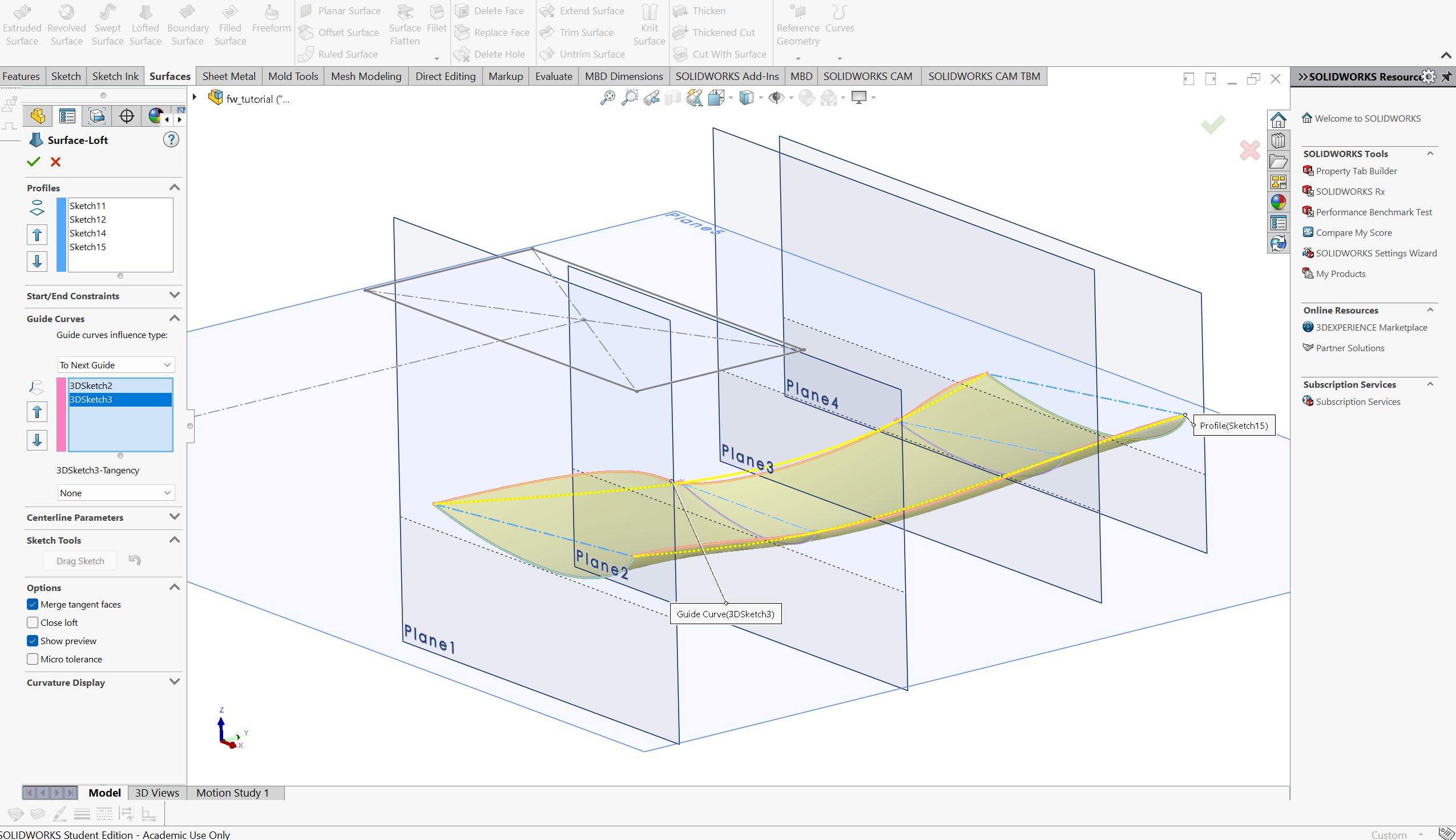
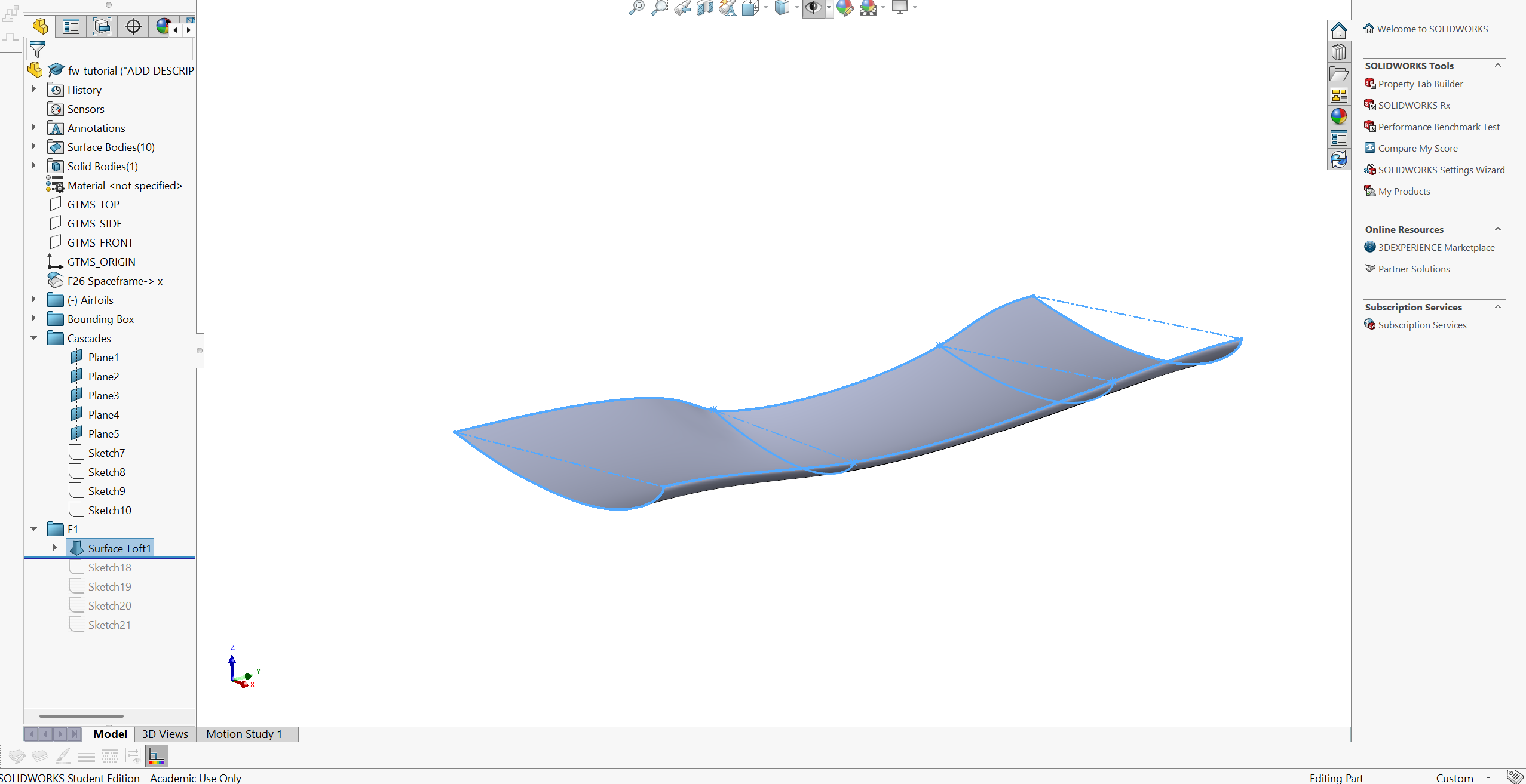
Ohhhh boy, here we go, the first surface. Go to Surfaces -> Lofted Surface. Select your half airfoil profiles as the "profile" sketches and the splines as the "guide curves":
Repeat these steps for the top of the wing. Be sure to re-use the splines for the guide curves, or just select the edges of the wing as the guide curves.
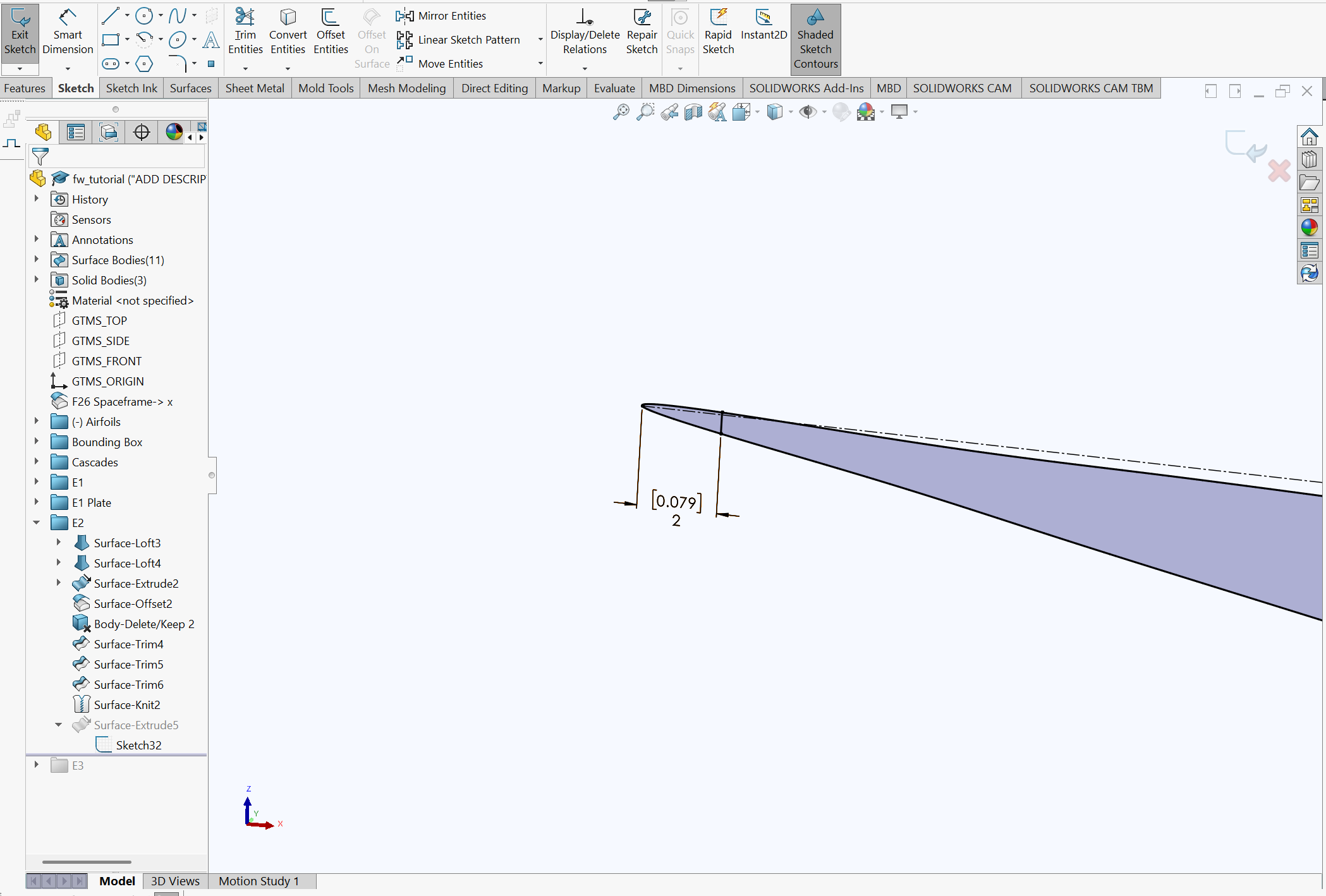
We need to Truncate the trailing edge to clean up the geometry in that area. There's a lot of reasons for this that I'm too lazy to actually go into, but just know this is important for both CAD quality and CFD meshing.
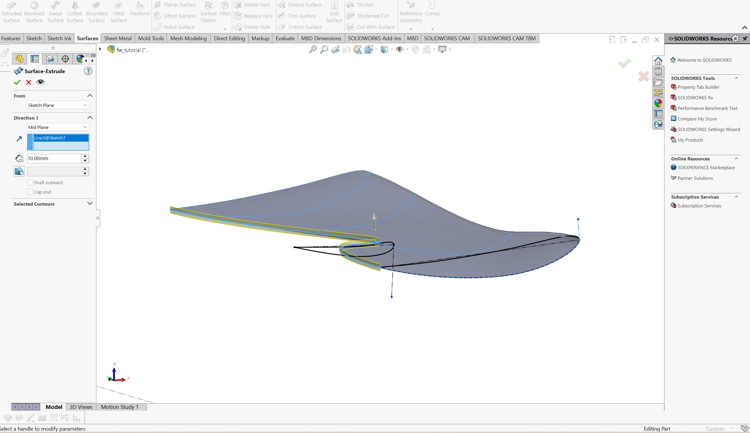
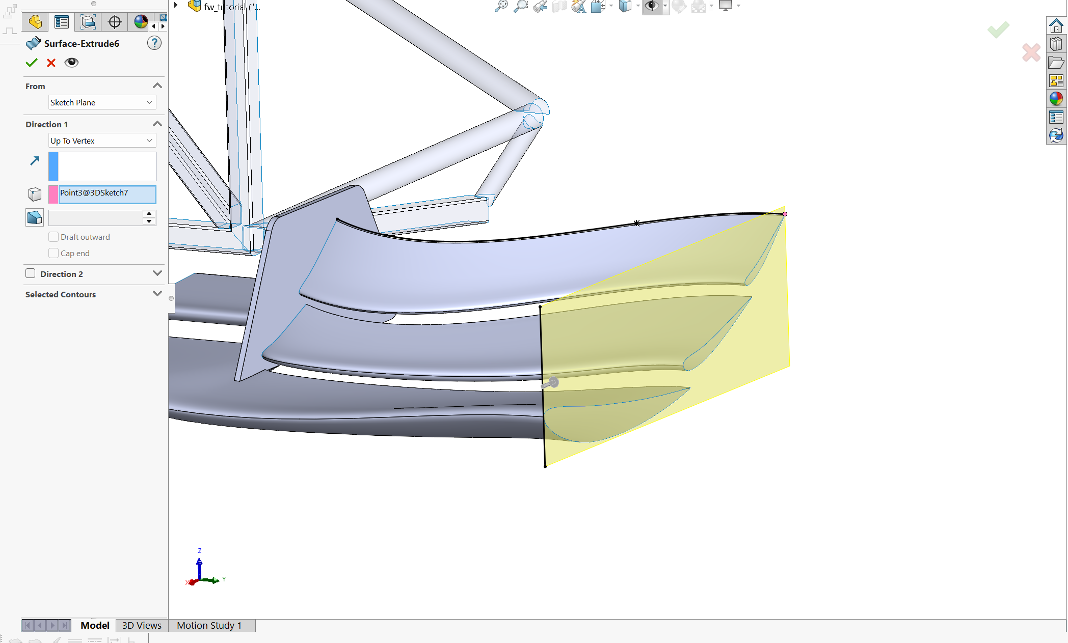
Select the spline you made for the trailing edge guide curve. Go to Surfaces -> Extruded Surface using this sketch
Select "Mid Plane" so that the sketch goes off in both directions. Doesn't matter how long, as long as its pretty long. You need to define a direction vector here, which you should select as one of the perpendicular lines to one of you airfoils.
Offset this surface 2 mm or so in the direction into the airfoil. You can hide or delete the initial surface
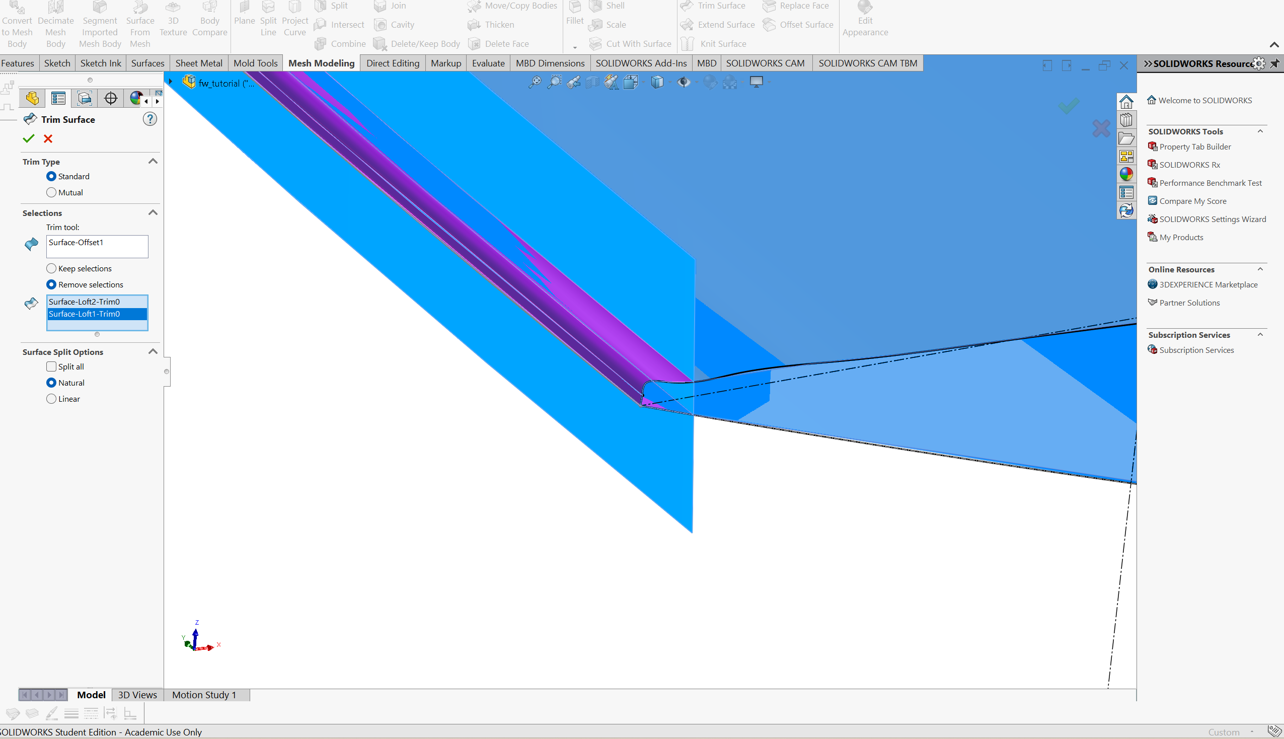
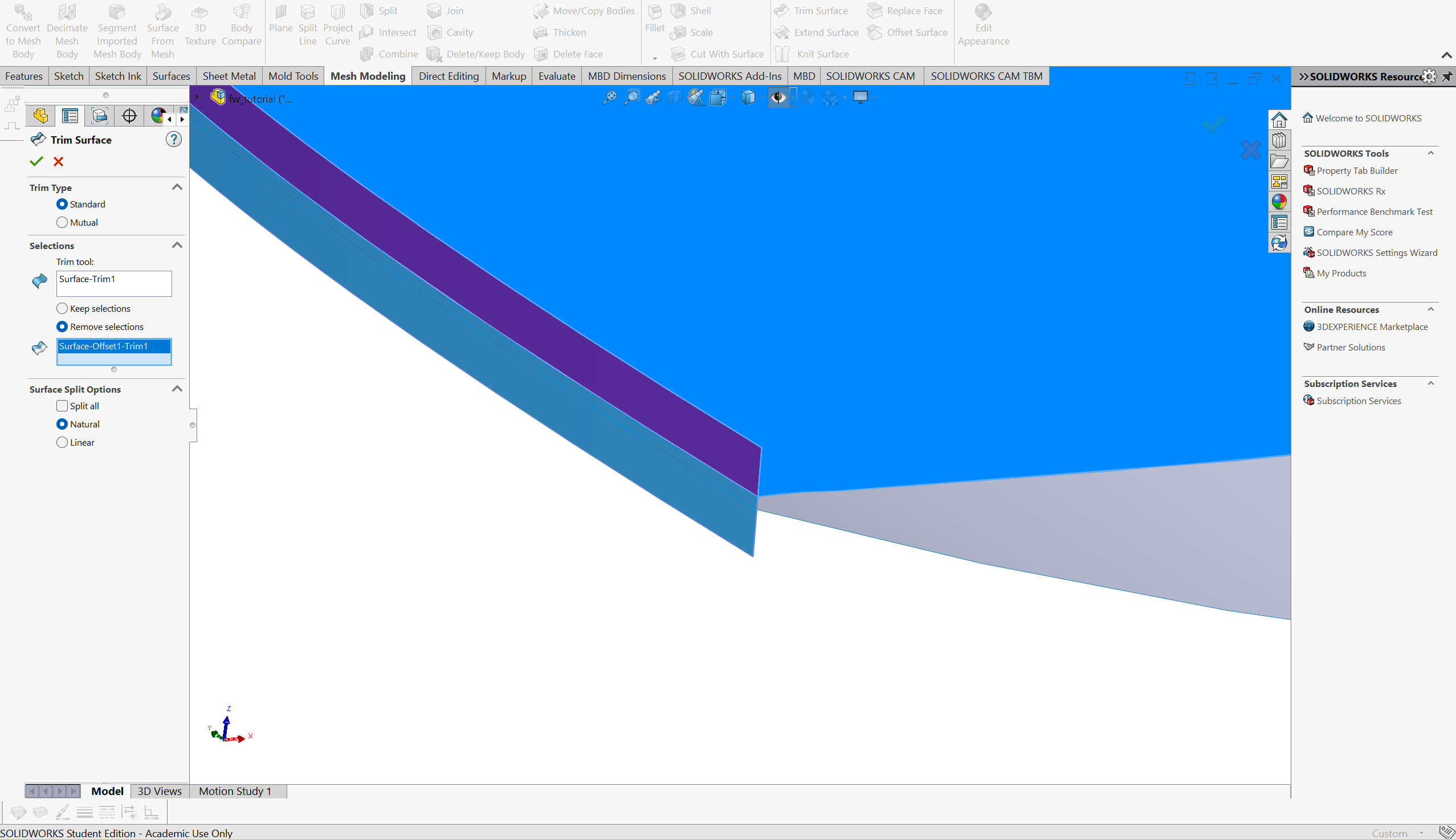
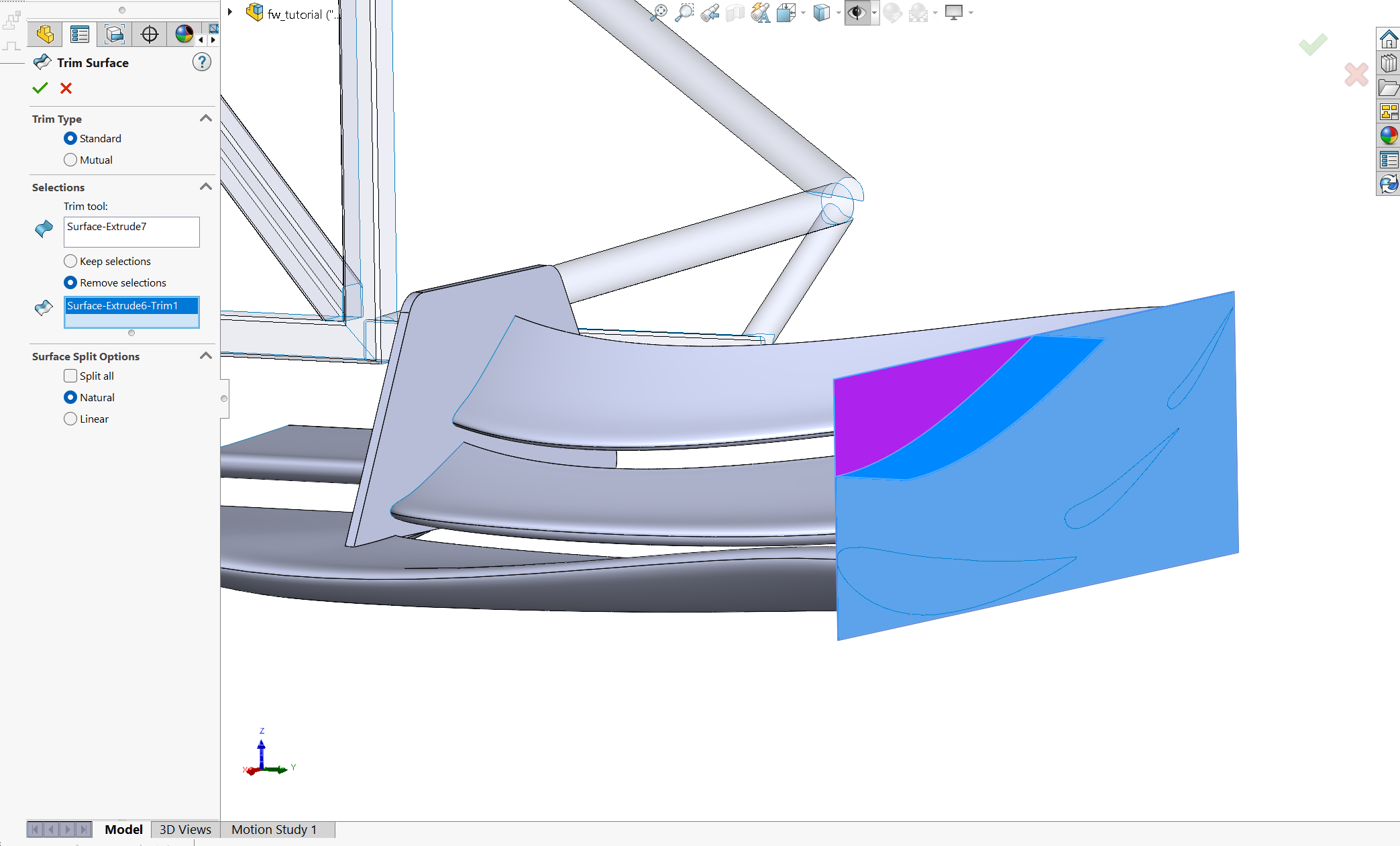
Go to "Trim Surface" and select the offset surface as the "Trim tool". Select the two surfaces (upper and lower) behind the offset surface as the remove selections.
You'll do two trim surface operations next. Select the top surface as the tool and remove the top excess surface like in the picture. Repeat for the bottom surface.
Knit the surfaces. Until the big mirror for the otherside and the endplate you kinda sorta made your first wing!
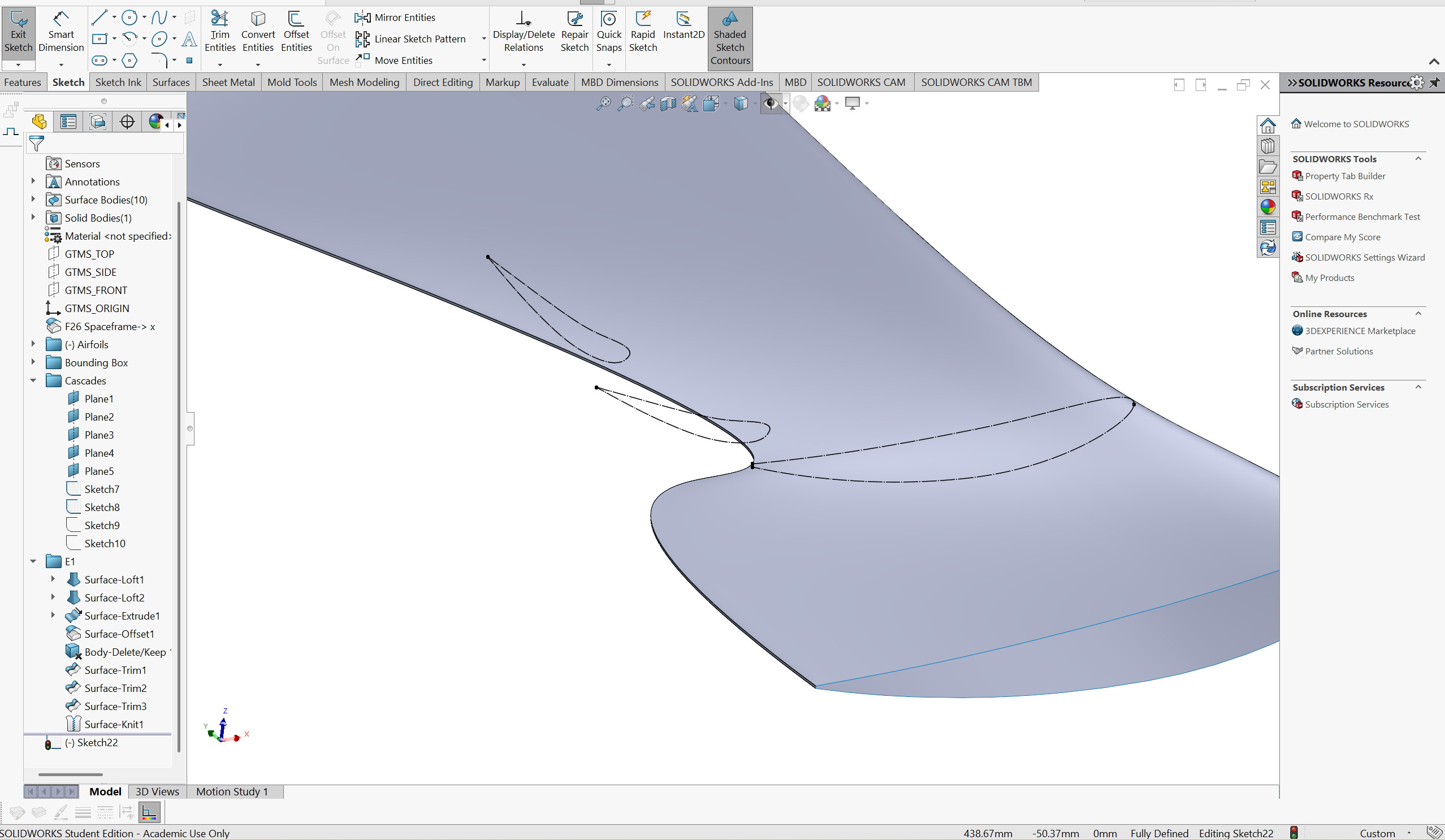
Of course, if you're a normal person that doesn't want to create a shape not even bob the builder could manufacture, you can also very simply extrude airfoils. On my part, I'm doing an extruded E2 element in the middle of my wing.
Instead of having to make a bottom airfoil and a separate top airfoil sketch, make a sketch that copies the entire airfoil you want to extrude from the cascade
Since we're extruding this airfoil, we don't care as much about preserving the original airfoil shape while we're constructing the wing like we do in the loft. What this means is that we can do the TE truncation on the sketch.
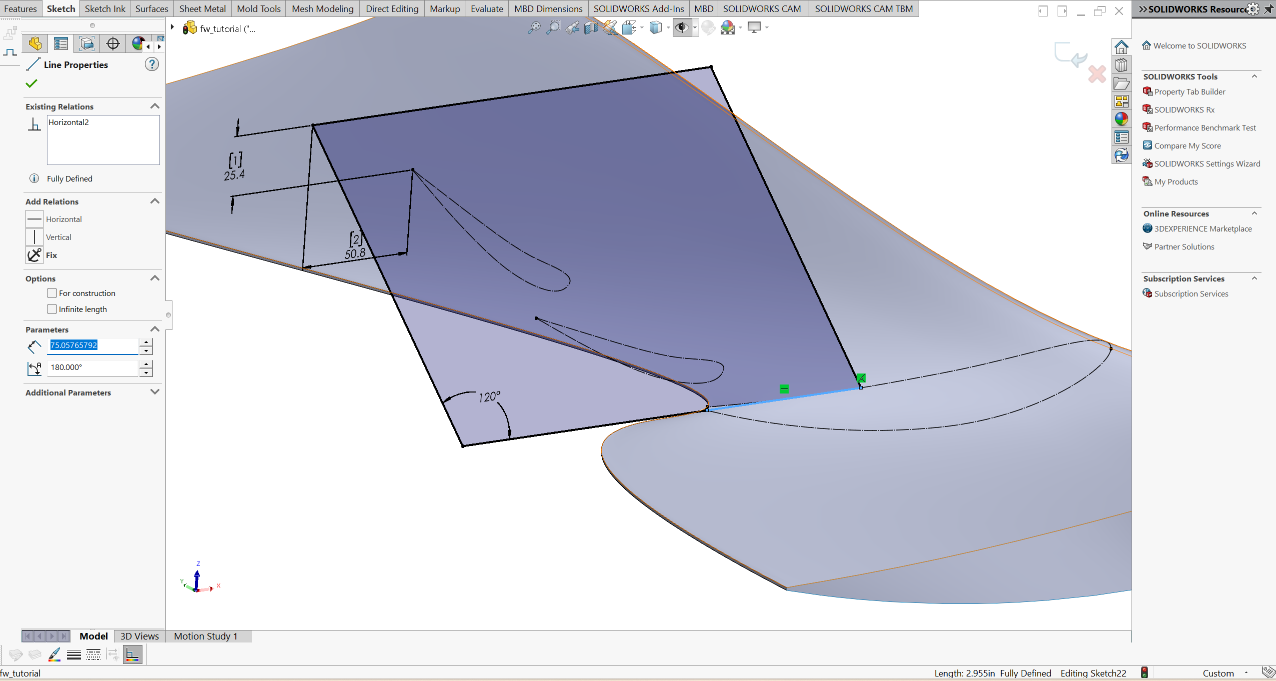
Fully define the airfoil you just copied over. Don't break any references, just re-make the lines or also copy them from the original sketch if they exist
Create a line that's perpendicular to the chord line attached to the upper and lower parts of the sketch. Offset the line ~2mm from the trailing edge point
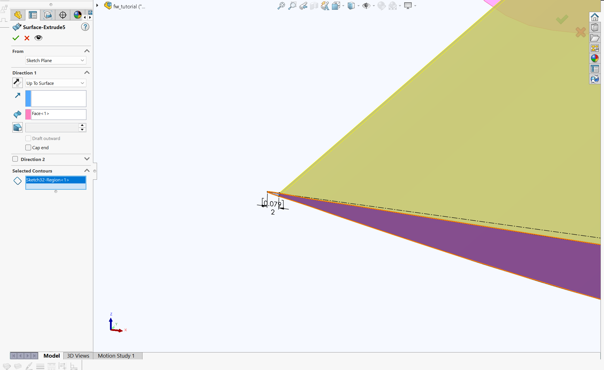
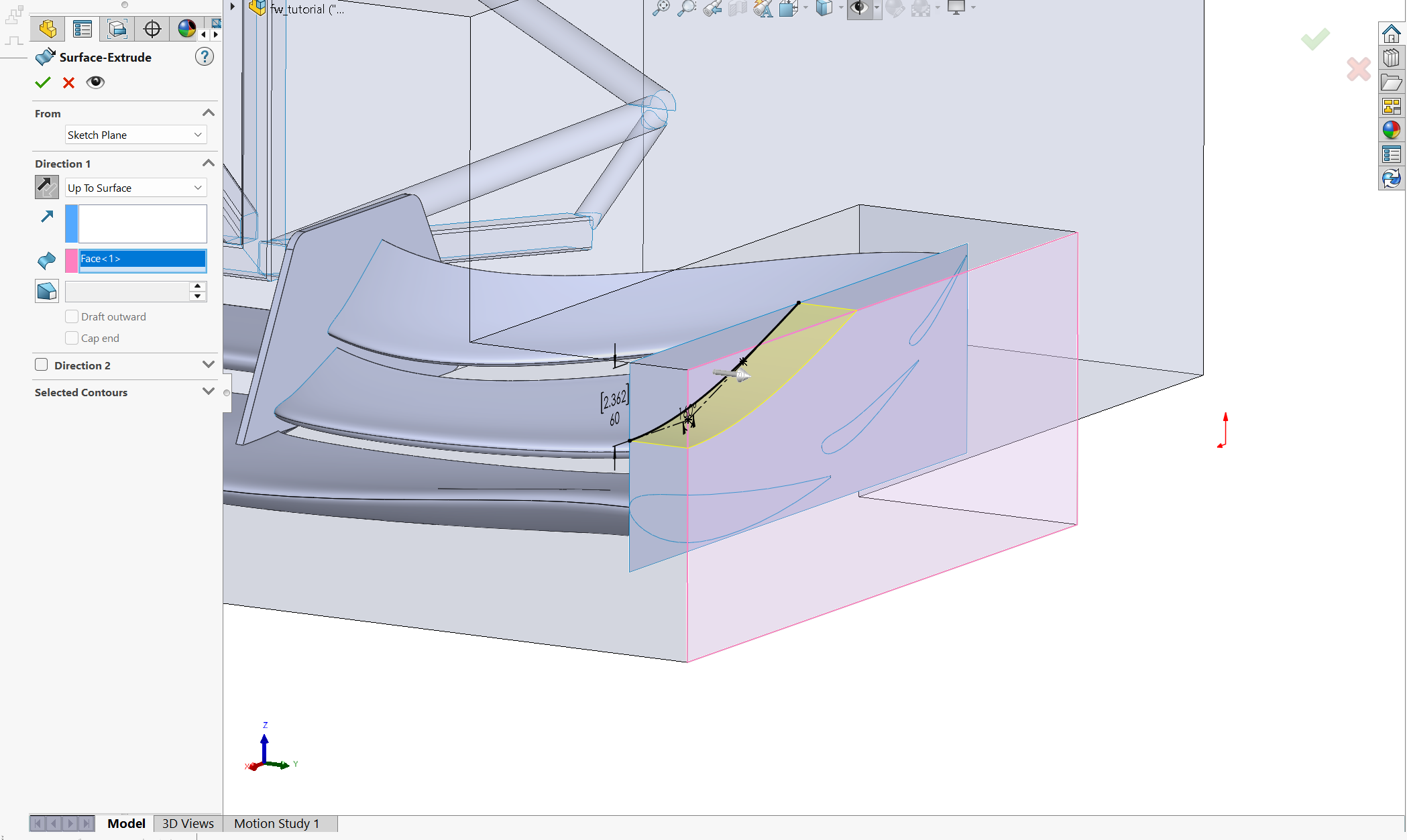
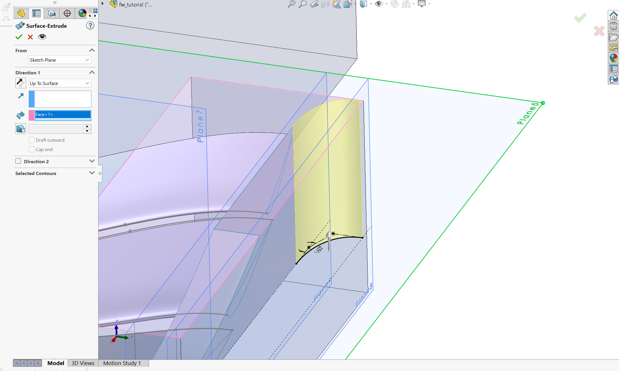
Surfaces -> Extruded Surface. You can select a bunch of options for where you want to extrude the airfoil to. This example has a sideplate (next section) so i select to extrude up to that surface. Select the contour of the sketch that doesn't include the truncated TE.
You'll see on a lot of wings (particularly front wings), not every wing is continuous across the span. For this to be possible, there needs to be some plate in between the endplates such that the airfoils can intermittently be mounted at these discontinuities. AGAIN, I'm not gonna touch on what happens with these aerodynamically, but just gonna show how to make one.
Create a sketch on the plane of the desired endplate. I conveniently defined my "plane 2" as a plane where i want a sideplate.
Hit "Convert Entities" on the elements in the cascade that haven't been constructed into a wing yet. In this case, E2 and E3 airfoils.
Hit the dropdown under convert entities for "Intersection Curve". Select the parts of the wing in the cascade. This will essentially be where your sideplate is mounted to.
Make everything a construction sketch. They're all there for reference.
Draw a random ass box. Make it look cool. The only geometry requirement here is that a part of the box goes through the wing, so that the sideplate can be cut to shape later.
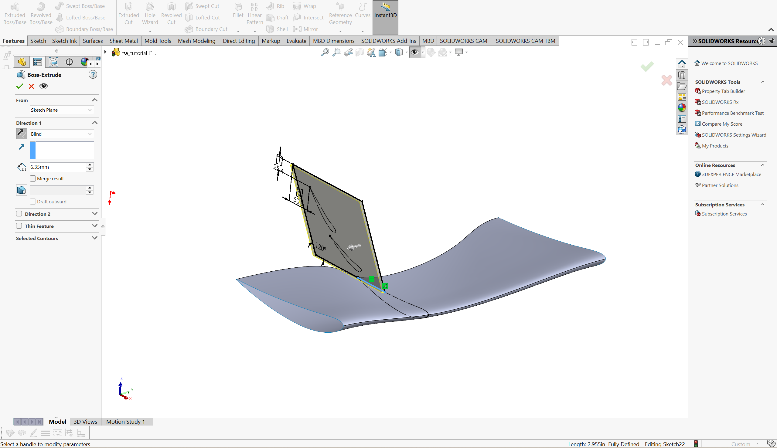
Conduct a boss extrude of 0.25 in. Make sure that measurement is correct, its the thickness of our flat panel carbon fiber and can change depending on what core or ply schedule is used. Or its not even carbon for some reason, idk.
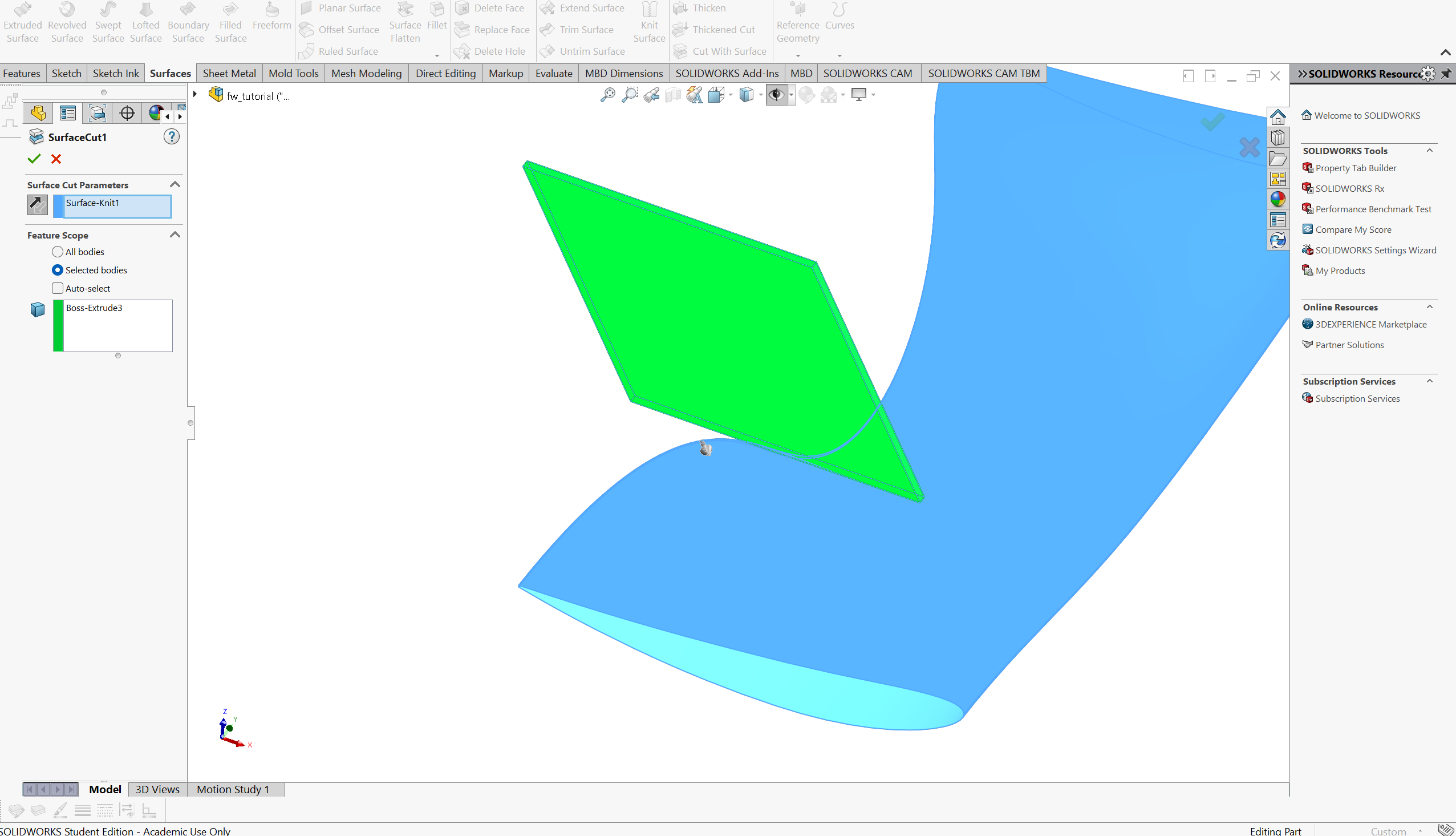
Perform a "Cut With Surface" Operation in the surfaces tab. Select the wing as the "Surface Cut Parameters" selection, and select the sideplate as the solid in the feature scope. Ensure the arrow is pointing into the wing (the stuff getting cut)
Clean it up with fillets and you're pretty much done
So, lets assume you followed the above steps to create the rest of your wings. Apologies in advance for not including steps and screenshots of my E2 and E3 construction, but you know what, frick you, i dont work for you or for anyone here. you have NO IDEA how bad uploading a single image to the wiki is. It's like signing a contract every time i need to show you where a button is.
Here's where i was able to get to after repeating the steps I've written down for other parts of my front wing:
There's one more thing we need. Endplate. This is the hardest part of the wing. The techniques necessary to construct different endplates are typically complex surface modeling techniques, unless you make a simple flat plate. We won't be doing that here, because 1. its not an optimal design and 2. I want to teach the highest level of CAD I can in this tutorial so as to allow members of this team in the future to create whatever they want. Here's some check-in questions and points to keep in mind as you're making your endplate:
Why is an endplate necessary? What does an ideal endplate do to pressure distribution over a wing?
How do I CAD an undertray? What techniques can I use during undertray CAD from surface modeling an endplate?
What's a vortex? How do vortices "seal" pressure regions?
To start, I made this little sketch to show you what geometry we'll be targeting:
The distinct features are a curved footplate section, a canard at the top, and a outward curve at the rear to promote outwash of the tire wake. The technique I'll be using for most of this endplate will involve surface extrudes, trims, and fillets to join different surfaces. Lets begin.
Make the base of the endplate. This will be a flat plate coincident to the wings. Create a line as far forward as the bounding box allows and complete a surface extrude back to around where the TE of the last element in the cascade is. It's crucial the connection between the endplate and the wings is flat, since we are (at least currently) restricted to 2-D internal structures.
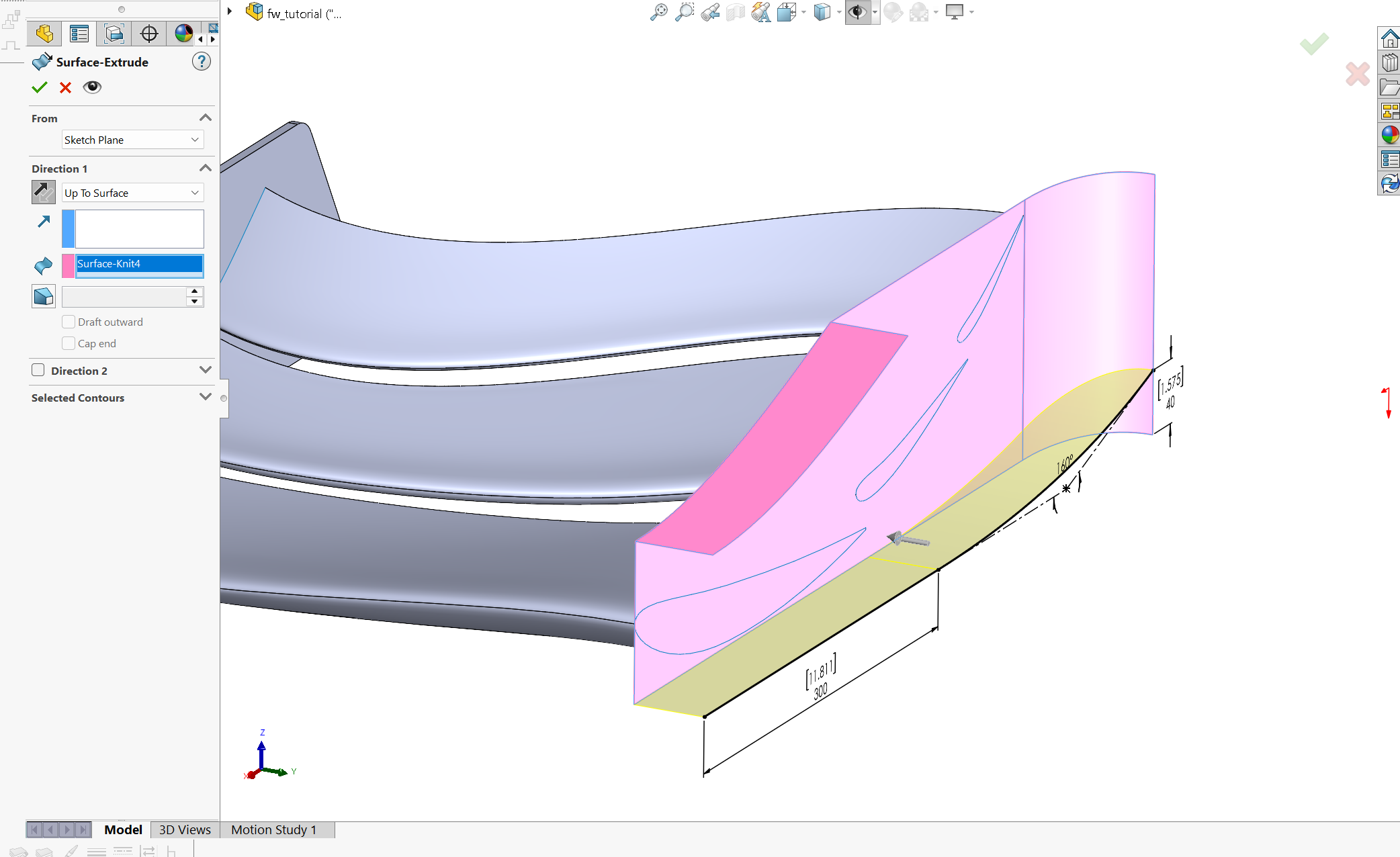
On that base plate, create a sketch to define the curvature of your canard. I chose to do a studio spline so the spline is easier to define. The dimensions I chose are pretty much arbitrary. Once defined, extrude the surface up to the maximum the bounding box allows.
We can now trim away the excess that isn't included on the endplate. The trim surface tool allows us to select the new canard as a trim tool and the removed section as the portion of the flat plate above the canard.
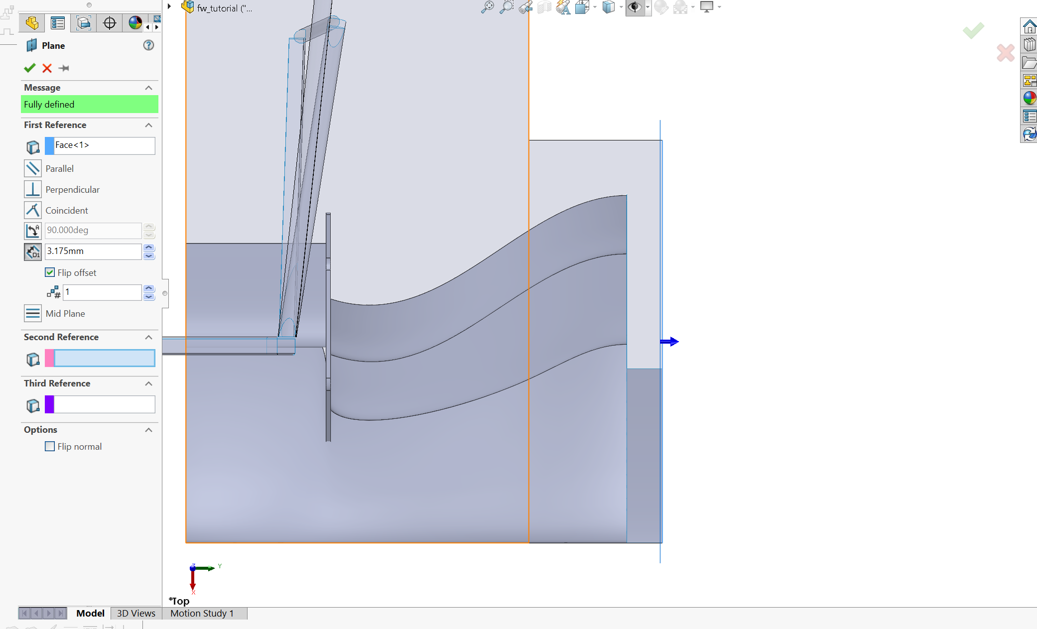
We now define an important plane for constructing the curved section and footplate. Let's assume this endplate will be made with 1/8" composite core, and that plus ~1/16" for the carbon is the exact thickness of the final part. This plane will be offset from the outside bounding box plane to reflect that thickness, so that when we do thicken our part its just at the edge of the bounding box.
Make a sketch on the minimum ride height plane and define your curved portion. Make another spline that begins at the end of the flat plate section. Extrude it up to the top of the bounding box.
Moving on to the footplate, we'll need two surfaces. The first one will be horizontal and the other vertical, together creating something that resembles a step. My horizontal line has a flat section all beneath the first element where the main suction peak is, then a slight curvature upwards. Extrude this sketch up to the existing endplate. Make sure you knit surfaces of the endplate together before moving on. The "up to surface" for this sketch requires the surfaces to be joined.
Use trim surface to remove the excess endplate surface beneath the footplate
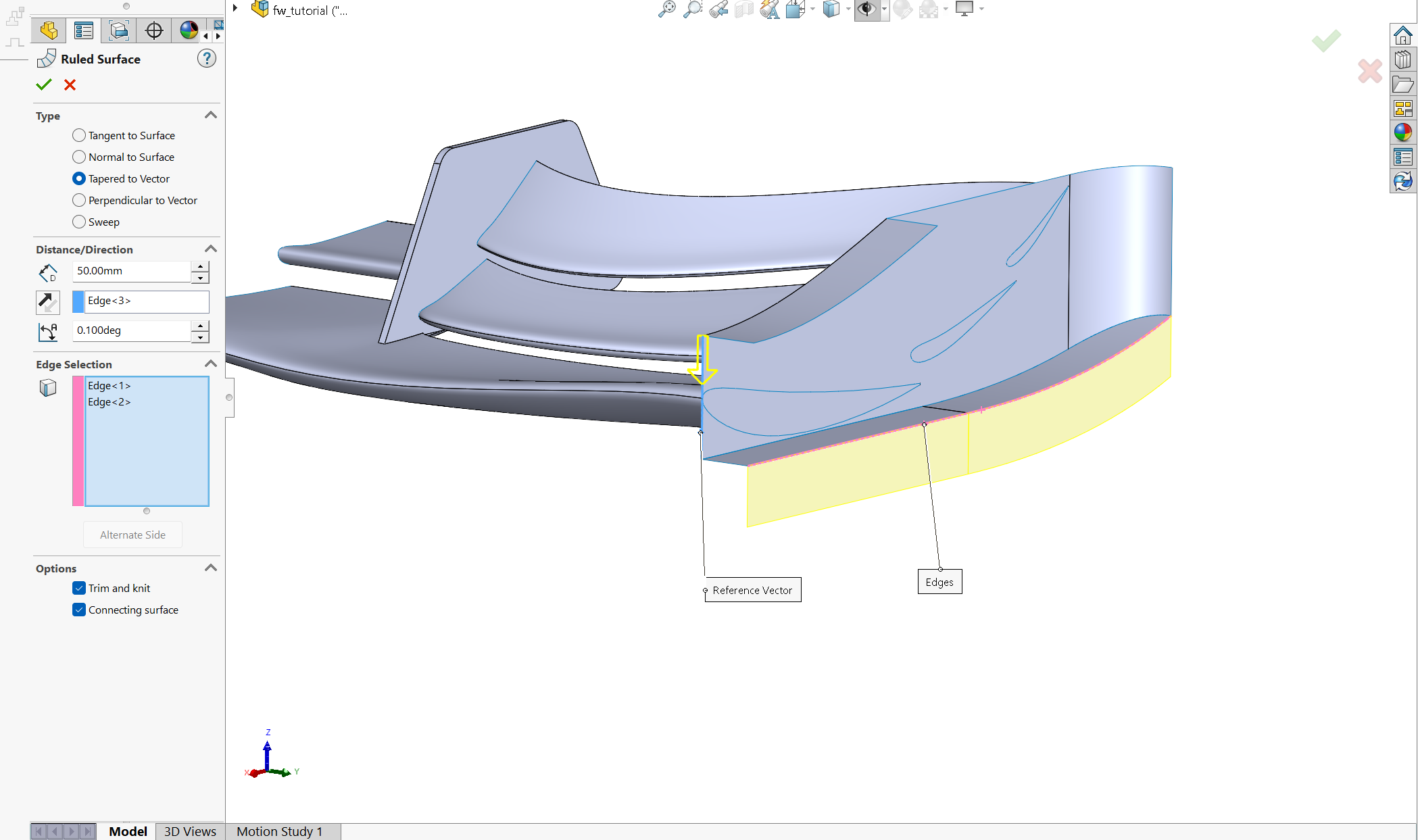
Go to Surfaces -> Ruled Surface. Select the "Tapered to Vector" option. Set the distance to some arbitrary big number. Select an edge that's perpendicular to the ground as your direction vector. Lastly, select the two edges of the footplate. This operation allows us to extrude a surface from an edge with a defined set of rules. This surface is our canvas for the edge of the footplate.
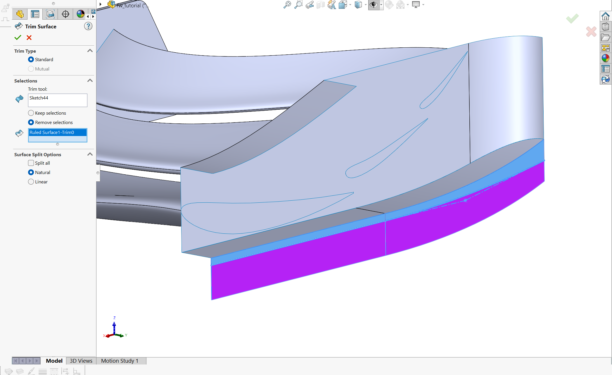
Create a sketch on that ruled surface. This sketch will serve as the trim tool for the part of the footplate you want to get rid of.
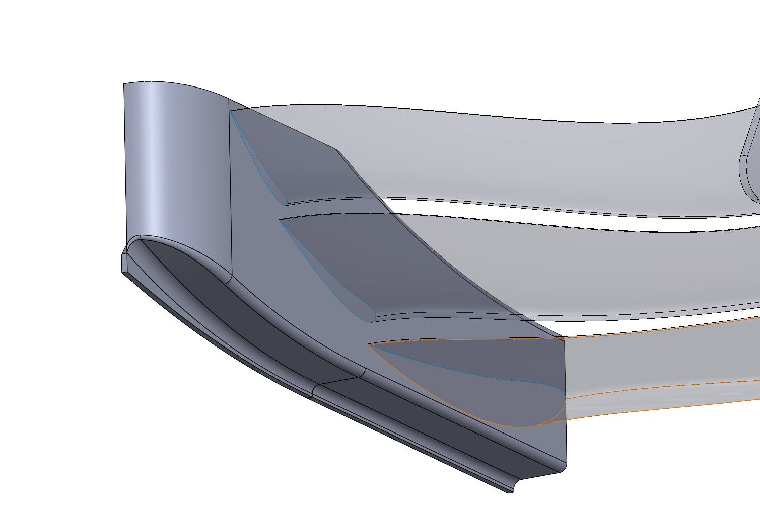
After this, its just knitting filleting thickening and then you're done. I will say filleting some of these corners can be difficult because the geometry is complex. Be patient, and just try different fillet sizes and different places. I don't think its worth walking through specifics on this; Every part is its own world of pain when it comes to surface cleanup. IF you complete every step, go to thicken, and get an error, firstly I'm sorry. Second at that point I'd probably just find a lead. Maybe that's me being lazy, or maybe my body temperature is 101 degrees fahrenheit.
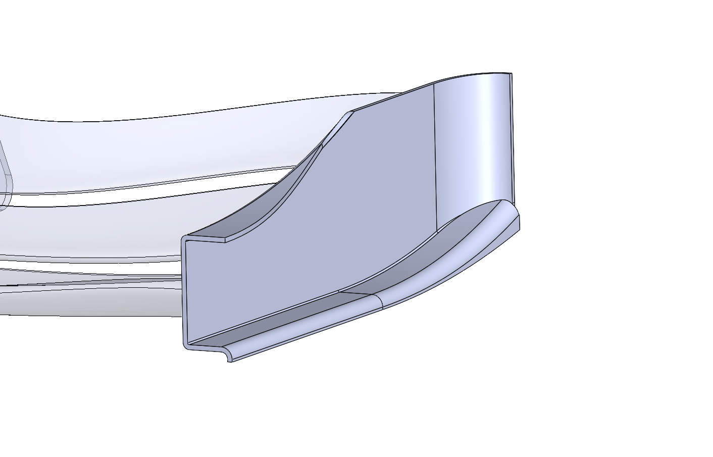
Here's my final product. (I cut away the canard in a step after making it, not too important):
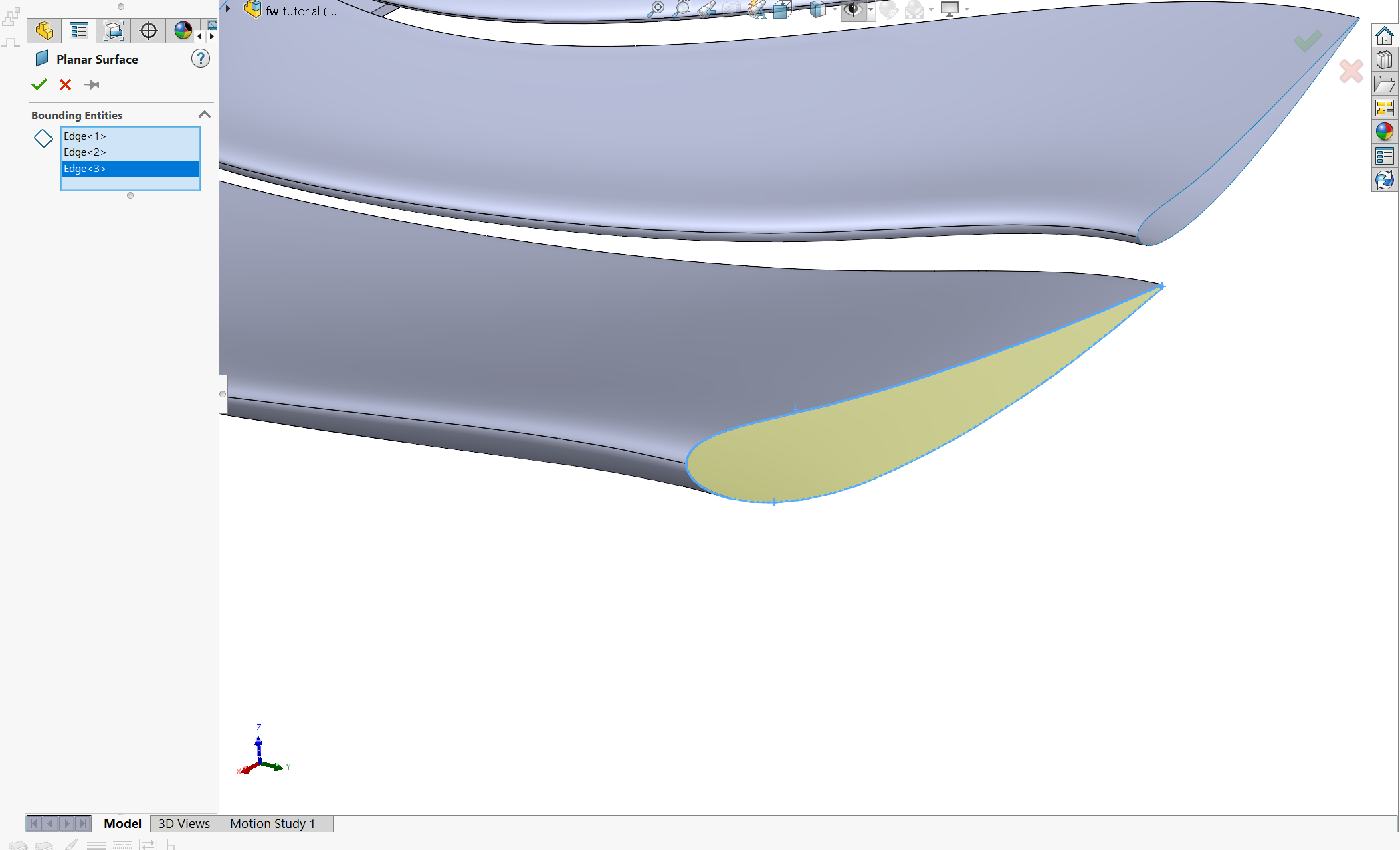
Alas, every part of your new front wing is designed. There are some finishing steps that are best practice for preparing this geometry for CFD simulation. Honestly, you probably could import stuff as-is after mirroring since STAR-CCM+ can import solid and surface geometry. Regardless, let me show you how to make a wing element into a solid (Only showing E1 here, but you'd do this for every element in the wing.
Hide the endplate. Go to surfaces -> planar surface. Select the three (yes, three, remember the TE is a sharp edge) edges of the airfoil at the end. You should see the surface filled. Execute the operation.
Knit the planar surface to the wing element
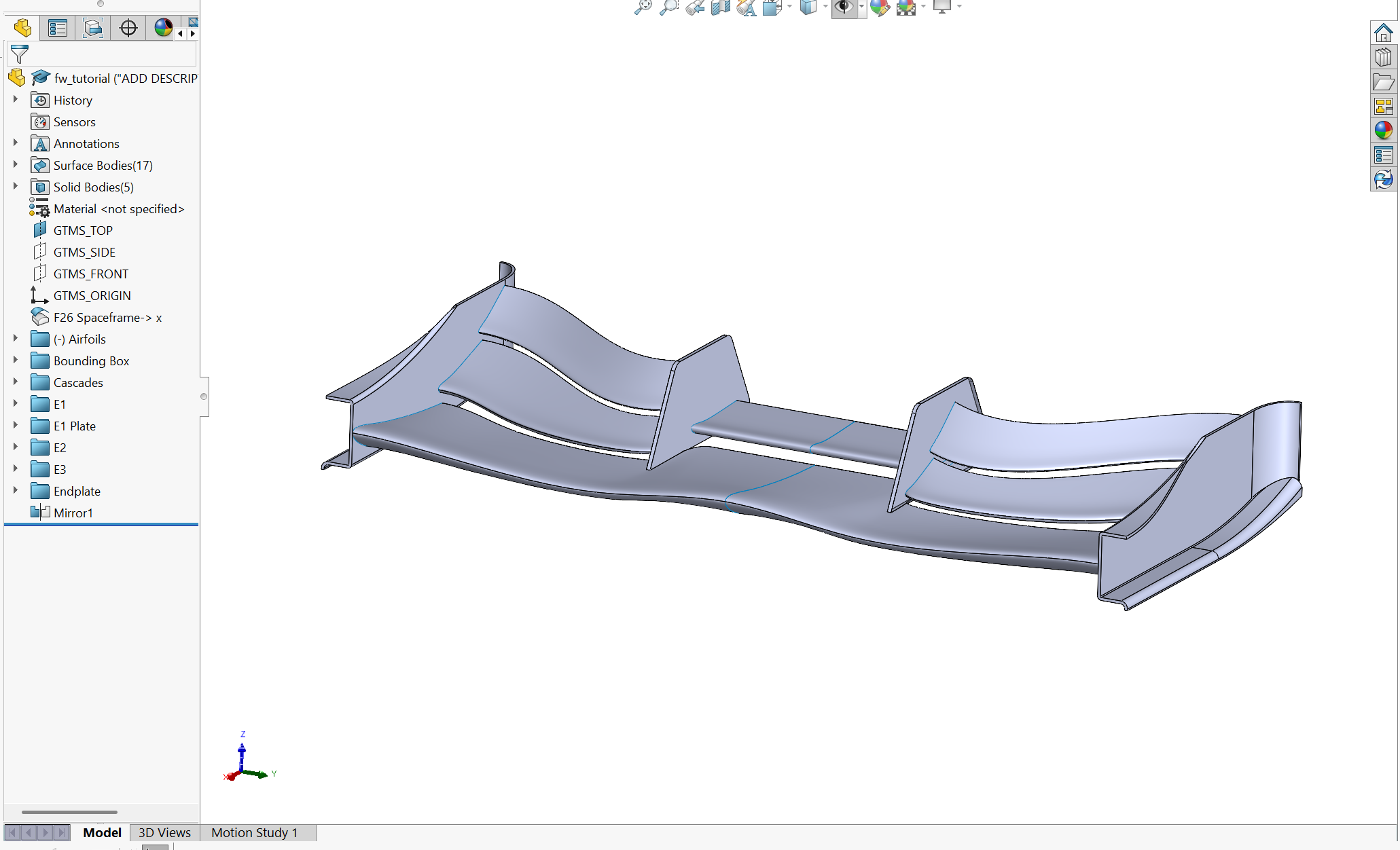
Mirror everything. My wing looks like this after that operation:(pretty bitchin right)
Knit the two halves of E1. When you do this, you should see the option to "create solid". This is because the two ends of the wing are now capped with the planar surface, so knitting the surface creates an enclosed volume. Click that an execute.
LADIES AND GENTLEMEN, BOYS AND GIRLS. MAY I PRESENT; THE COMPLETED FRONT WING