GTMS leverages an open-source software called XFLR5 for design and simulation of 2D Airfoils. Download the latest or most recommended version. Your computer will likely give you a warning that the software isn't safe. It is, just hit the more info button to allow it to run. Follow the steps below to create and analyze a two-dimensional airfoil.
Open XFLR5. You'll be met with a blank screen
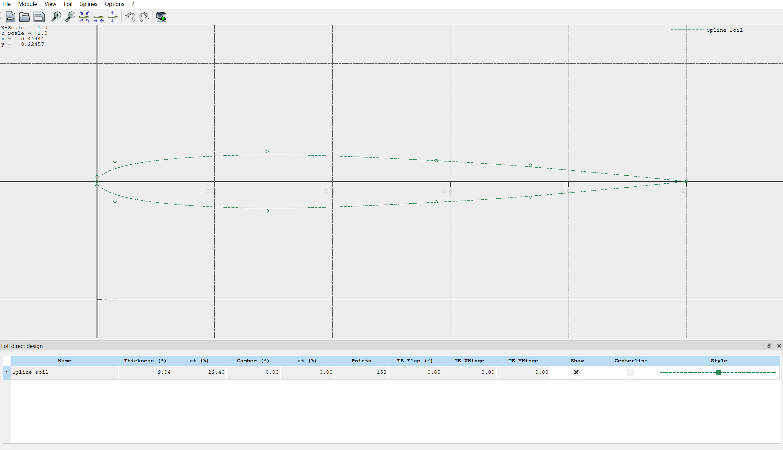
Navigate to Module -> Direct Foil Design at the top left of the screen. You should see an interface that looks like this:
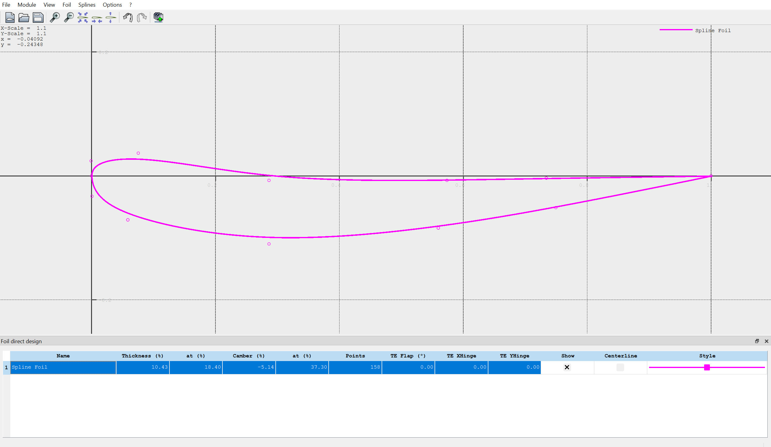
Click to drag the points you see on screen to make a new spline shape. Yes, it will likely look like a mess your first time making one. You likely barely know what a "good" airfoil is supposed to look like. That's okay! We have resources for that, and this tutorial is just to get familiar with the design procedure. Here's what mine looks like, if you want a reference:Note that you can change the appearance of your spline by clicking on the "style" tab on the table below your airfoil.
Navigate to Splines -> Store Splines as Foil in the top left. Enter a name with the naming convention (initials)_(type)_(descriptor). Type for our case is sort of ambiguous, but know that "primary", "secondary", and "tertiary" are common designations for the first, second, and third elements of a wing. They are usually abbreviated as "P", "S", and "T". Equally as valid is element 1, element 2, and element 3 which shorten to E1, E2, and E3 respectively. I named the above airfoil "JD_E3_Example".
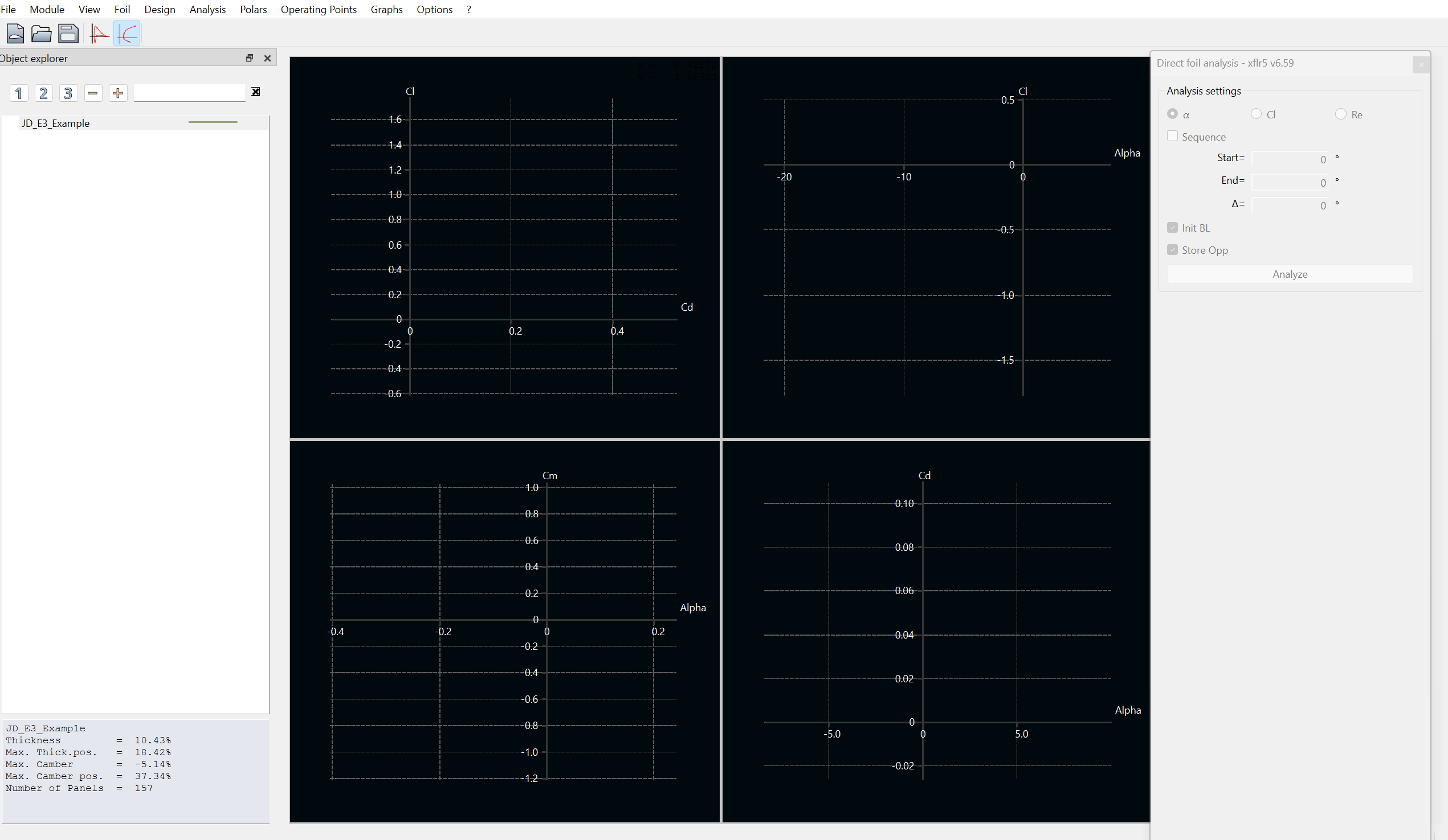
Navigate to Module -> Direct Foil Analysis. You'll see an interface that looks like this:
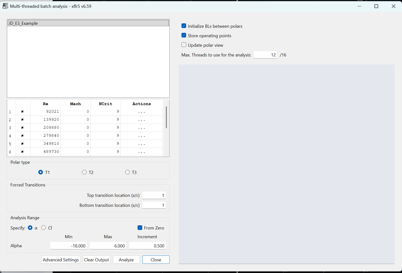
Navigate to Analysis -> Batch Analysis. It may be a bit confusing for those less experienced from here. Batch analysis allows us to test our airfoil at multiple angles of attack and at multiple Reynolds Numbers. The UI will look like this: First, set Min Alpha to -18 and Max Alpha to 6. This defines the range of angles of attack we simulate. Change the increment to 0.500. For Reynolds Numbers, calculate a good range of numbers between 10 and 60 mph at sea level conditions. Assume a characteristic length of 1 m. Use the 1976 Standard Atmosphere Calculator to determine dynamic viscosity and density at sea level. One of my personal favorite websites that one, love the little fishes they have at the top. Click the checkbox for Initialize BLs between polars and Store operating points. Change the number of threads such that your computer has four threads available. finally... HIT ANALYZE
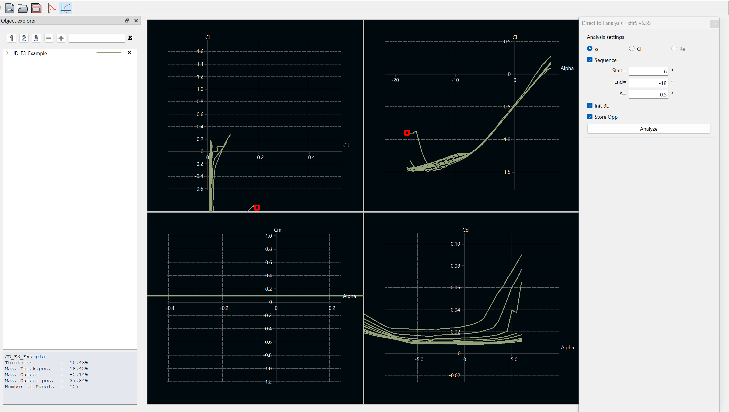
Exit out of the batch analysis window. You should see the graphs populated with data like so: Now what? You just completed your first airfoil simulation! Click and drag the graphs to bring more data into view. Click the dropdown on the left hand side (in the screenshot, the row that says "JD_E3_Example". Clicking the x's will show or hide the data for a specific Reynolds Number of a specific angle of attack point.
SAVE YOUR PROJECT. I didn't, literally just as I was making the tutorial, and lost my progress.
Check-in questions before moving to the next section:
What is the general trend of Cl versus alpha? Linear? Exponential?
What is Cl or Cd anyway?
What is the trend for Cd versus alpha?
How do these relationships correlate? E.g., what is the relationship between Cl and Cd? Is there a point at which that relationship changes?
How do the trends differ for different Reynolds Numbers?
How can I improve airfoil lift? How can I reduce drag?
XFLR5 Export / Solidworks Import
Now that you've designed an airfoil and completed analysis on it, its time to take it to Solidworks. Follow the steps to obtain a generic sketch in Solidworks with your airfoil profile.
Clone a local view of "Airfoil-.DAT-Inverter" from GitHub. This section will require you to create a GitHub enterprise account with your Gatech account information. Once this account is created, message a lead asking for GitHub access. They'll need to send you an invite to join the organization. Once you're on, here's the steps to make a local view:
Open command prompt and navigate to a directory in which you want this Matlab tool (cd "C:\ahoosian45\Example_Folder\")
Run the command "git clone https://github.com/username/repo.git subfolder-name", where the URL is the URL of the repository online
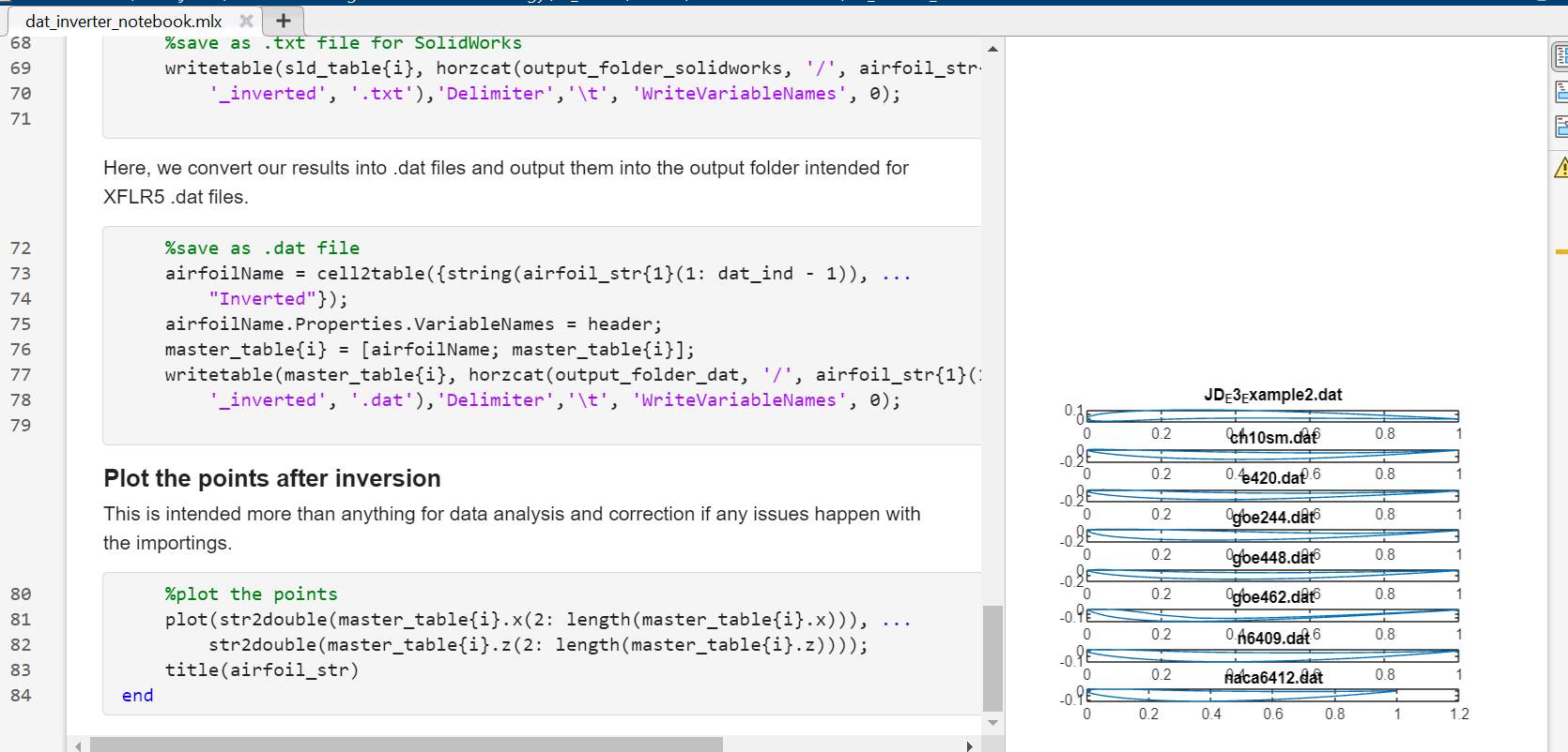
Open "dat_inverter_notebook.mlx" in Matlab. This is the main live script that will take the exported .dat file from XFLR5, scale the values, and convert to .txt which is readable by Solidworks.
Lets go back to XFLR5. To export your spline, navigate to Splines -> Export Splines to File. Save the .dat file with the same name as the spline to the directiory "...Airfoil-.DAT-Inverter/input_airfoils"
Hit run on the entire "dat_inverter_notebook.mlx" script. At the end of the script, you'll see a bunch of graphs with some example airfoils and your new airfoil. If you don't see your airfoil, you did something wrong.
Open Solidworks. If you haven't already, follow this onboarding document to setup the proper GTMS Solidworks Templates
Create a new GTMS part
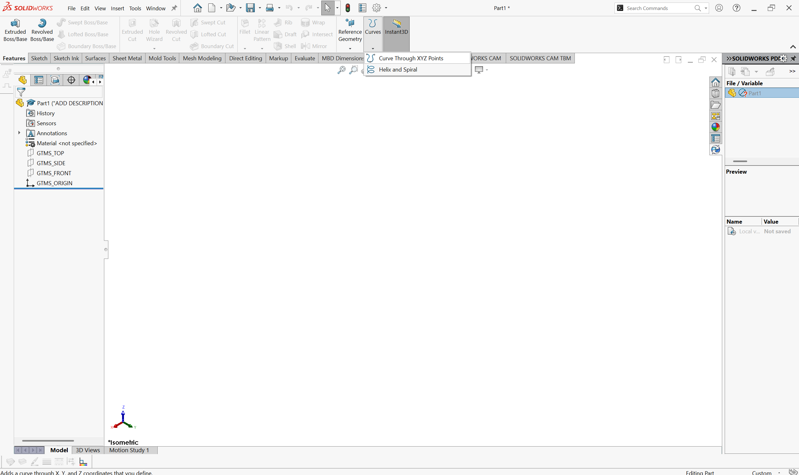
Navigate to Features -> Curves -> Curve through XYZ Points. You are not creating a sketch yet. curve import is a feature outside of sketch creation.
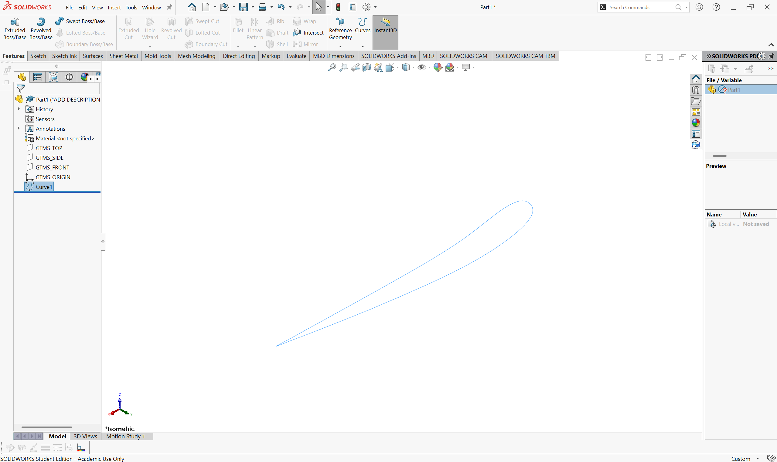
Hit "Browse" and navigate to the folder "......Airfoil-.DAT-Inverter/solidworks_txt". You should see your converted spline .txt file in this folder. Select it and hit ok
Tada!
3-D CAD / Wing Construction
The airfoil profile is the only import component necessary to construct CAD of your front wing. This generally applies to all aerodynamic parts, as any other element you need can be constructed by curvature you design.
DISCLAIMER: CAD is hard. This tutorial is not intended to be an "introduction to CAD". The steps should be clear enough to follow as a beginner, but at times will likely feel un-intuitive if you're knew to CAD.
Sketching and Ideas
When in a design cycle, you really should try to draw or document your ideas before you CAD them. There's a few reasons as to why;
Figure out what it is you're actually thinking. Too often, even with myself, aero engineers have an idea for a part, spend a day trying to get the CAD to work, and end up with something completely different to what they originally thought of. Corners are often cut just to make the part quicker. When you can help it, avoid doing this by sketching so you know exactly what CAD you want. What dimensions are important? What curves will define my part? Decide this before throwing darts at the CAD board.
Decide on structures and manufacturing points. Can we even build this? It's okay to design parts that are floating for aero development, but you should have at least one idea in your mind on how this would eventually be attached to the car. There is no point otherwise.
Is it stupid. Stupid is relative, but sometimes drawing out a part makes it a LOT more clear as to what you can accomplish. Say you want some crazy endplate design. When you try to draw it out, you should be able to see how the dimensions of the design work with each other, and what parts need to be compromised. Do things actually align with, say, the tire or the sidepod inlet? If, instead, you draw it out and what you're able to achieve looks like spaghetti in space, its probably dumb to some degree.
tl;dr do a drawing so you know the part works before CADing. No specific tips or steps here, every design has their own process.
Bounding Box
We'll be working with the CAD file you've just imported your airfoil into. The first step in a design is understanding your constraints. We'll put these into your part now.
The "bounding box" is a design space for aerodynamic components in FSAE. The box is outlined in section T.7 of the FSAE rules. The box is largely dictated by wheel position, so we must define that first.
Create a sketch on "GTMS_TOP". The origin of the part is located on the ground plane and is on-plane with the vertical front axle plane. This means that we can define track width using the origin as the midpoint. Create a centerline that does so.
Dimension the line to 48 inches. This is the base track width for the majority of our cars.
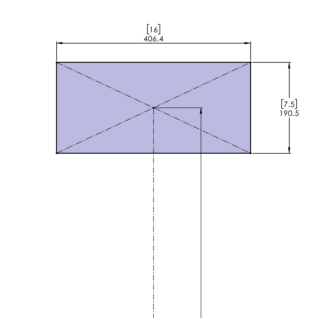
Create a rectangle based on the size of our tires. We use the 16x7.5" Hoosier R20's (Last updated 10/27/2025). This sketch serves as the "shadow" of our tire.
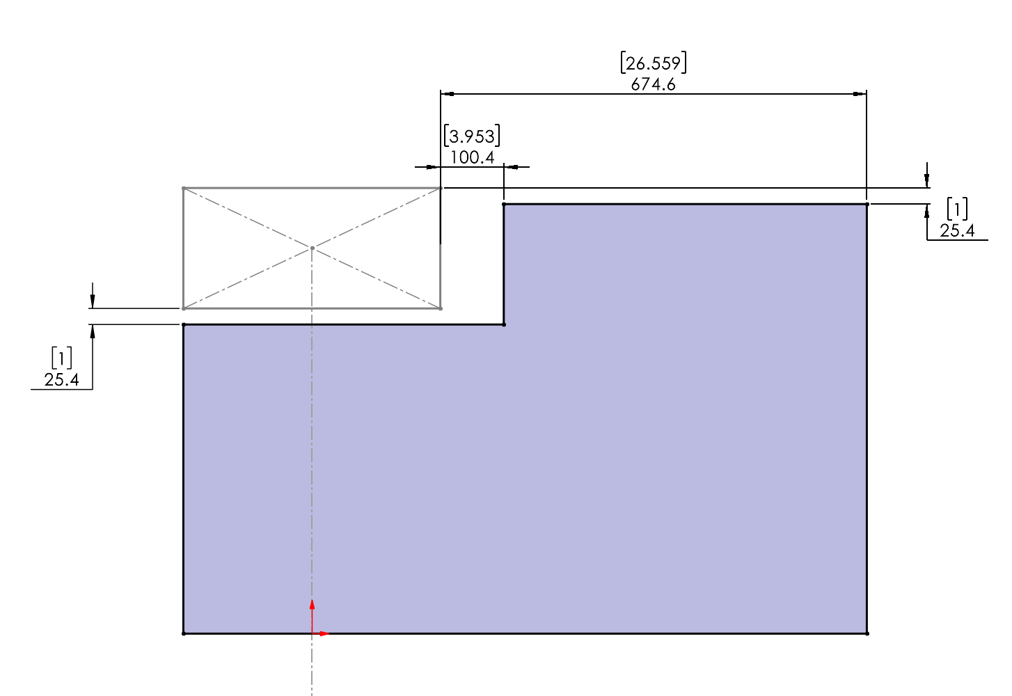
Create another sketch on "GTMS_TOP", which represents our ground plane. Make this sketch while referencing the rules to ensure the bounding box lines up. Ask yourself what is the reason for adding 1 inch of clearance to the actual rules.
Extrude the box upwards by 250 mm minus 1 inch
Make a sketch on the top of the new box. Highlight the top of the box and go to Sketch -> Convert Entities
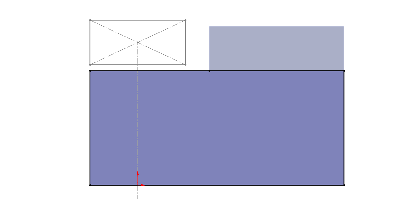
Use the trim and line tools to create a rectangle that looks like this:
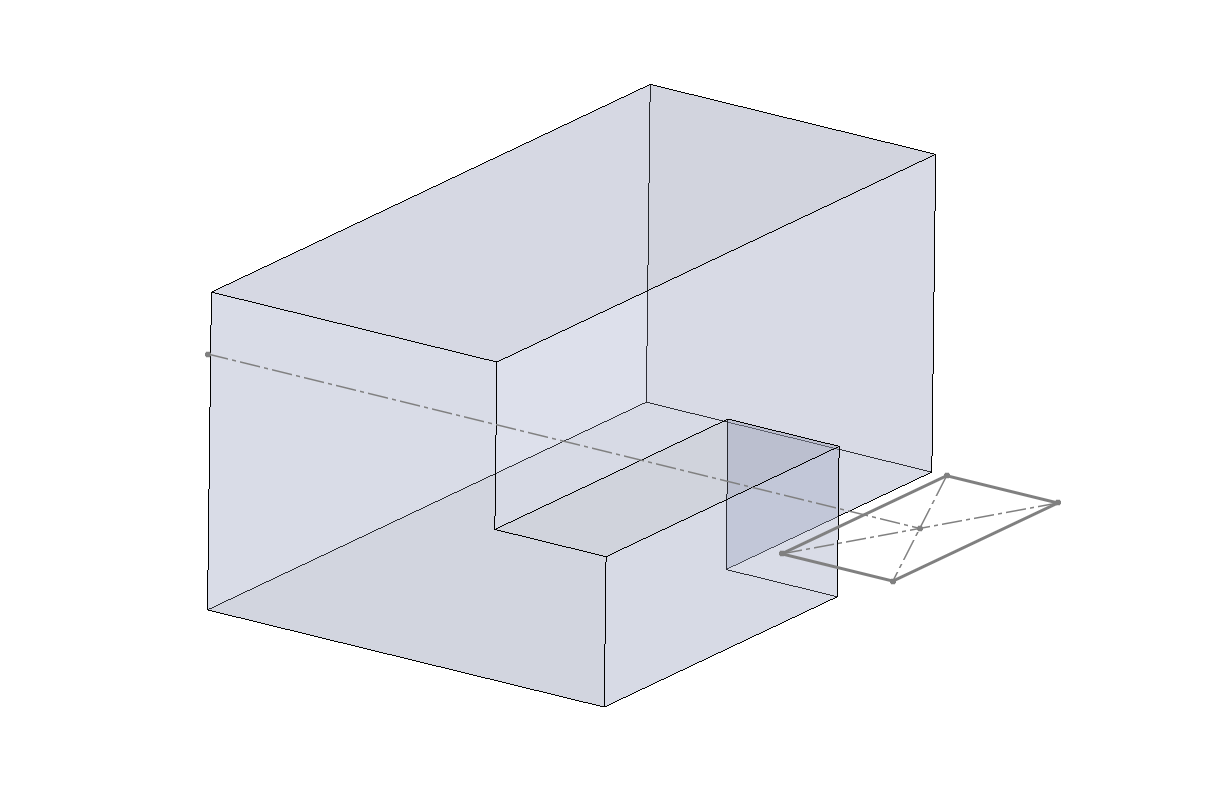
Extrude this box by 250mm
Go to solid bodies and right click the box. Make the box transparent.
Your front wing bounding box is now complete with 1 in. tolerance in all dimensions
References
Another crucial constraint we need to model is interferences with the rest of the car. Below is a methodology for importing reference surfaces for the rest of the car into the part file.